KS4009 KS4010 Keyestudio Micro: bit 45 in 1 Sensor Learning Kit

1. Description
The micro: bit is a mighty, and programmable computer designed by the BBC. Only half the size of a credit card, it integrates onboard Bluetooth, an accelerometer, a compass, three buttons, a 5x5 LED matrix, a USB interface and connection pins.
To bring computer science education and STEM topics to every student, keyestudio group launched this kit in consisting of a sensor shield fully compatible with micro:bit and other commonly used sensor modules.
In addition, this sensor kit also provides various learning projects for you, including wiring diagram, source code and more. It make learn and enjoy the programming easily.
2. Kit List
No. |
Mode |
QTY |
Picture |
|---|---|---|---|
1 |
Keyestudio Micro bit Sensor Shield V2 |
1 |
|
2 |
keyestudio White LED Module |
1 |
|
3 |
keyestudio Red LED Module |
1 |
|
4 |
keyestudio 3W LED Module |
1 |
|
5 |
keyestudio RGB LED Module |
1 |
|
6 |
keyestudio Analog Temperature Sensor |
1 |
|
7 |
keyestudio Photocell Sensor |
1 |
|
8 |
keyestudio Analog Sound Sensor |
1 |
|
9 |
keyestudio Analog Rotation Sensor |
1 |
|
10 |
keyestudio Passive Buzzer module |
1 |
|
11 |
keyestudio Active Buzzer Module |
1 |
|
12 |
keyestudio Digital Push Button |
1 |
|
13 |
keyestudio Digital Tilt Sensor |
1 |
|
14 |
keyestudio Photo Interrupter Module |
1 |
|
15 |
keyestudio Capacitive Touch Sensor |
1 |
|
16 |
Keyestudio Traffic Light Module |
1 |
|
17 |
keyestudio Hall Magnetic Sensor |
1 |
|
18 |
keyestudio Line Tracking Sensor |
1 |
|
19 |
keyestudio Infrared Obstacle Detector Sensor |
1 |
|
20 |
keyestudio PIR Motion Sensor |
1 |
|
21 |
keyestudio Flame Sensor |
1 |
|
22 |
keyestudio Crash Sensor |
1 |
|
23 |
keyestudio Analog Gas Sensor |
1 |
|
24 |
keyestudio Analog Alcohol Sensor |
1 |
|
25 |
keyestudio Reed Switch Module |
1 |
|
26 |
keyestudio Water Sensor |
1 |
|
27 |
keyestudio Soil Humidity Sensor |
1 |
|
28 |
keyestudio LM35 Linear Temperature Sensor |
1 |
|
29 |
Keyestudio Vibration Sensor |
1 |
|
30 |
keyestudio Thin-film Pressure Sensor |
1 |
|
31 |
keyestudio GUVA-S12SD 3528 Ultraviolet Sensor |
1 |
|
32 |
keyestudio 1602 I2C Module |
1 |
|
33 |
keyestudio TEMT6000 Ambient Light Sensor |
1 |
|
34 |
HC-SR04 Ultrasonic Module |
1 |
|
35 |
keyestudio Joystick Module |
1 |
|
36 |
keyestudio Micro Servo |
1 |
|
37 |
keyestudio Single Relay Module |
1 |
|
38 |
keyestudio Steam Sensor |
1 |
|
39 |
F-F Dupont Jumper Wire 40pin |
1 |
|
40 |
USB Cable |
1 |
|
41 |
Premium Battery Holder 6-cell AA |
1 |
|
42 |
Keyestudio Knock Sensor Module |
1 |
|
43 |
Keyestudio Digital IR Receiver Module |
1 |
|
44 |
Keyestudio Magic Light Cup Sensor |
2 |
|
45 |
Keyestudio 0.96inch OLED Module |
1 |
|
46 |
Keyestudio L9110 Fan Module |
1 |
|
47 |
Keyestudio DHT11 Temperature and Humidity Sensor |
1 |
|
48 |
Keyestudio 18B20 Temperature Sensor |
1 |
|
49 |
Keyestudio IR Remote Control |
1 |
|


KS4010
50 |
Keyestudio BBC Micro bit motherboard |
1 |
|
|---|---|---|---|

The micro bit motherboard is not included in KS4009 kit
3.Introduction
3.1 What is Micro:bit?
Designed by BBC, Micro:bit main board aims to help children aged above 10 years old to have a better learning of programming.
It is equipped with loads of components,including a 5*5 LED dot matrix, 2 programmable buttons, a compass, a Micro USB interface and a Bluetooth module and others. Though it is just the size of a credit card, it boasts multiple functions. To name just a few, it can be applied in programming video games, making interactions between light and sound, controlling a robot, conducting scientific experiments, developing wearable devices and make some cool inventions like robots and musical instruments, basically everything imaginable.
This new version, that’s the version 2.0, of Micro:bit main board has a touch-sensitive logo and a MEMS microphone. And there is a buzzer built in the other side of the board which makes playing all kinds of sound possible without any external equipment. The golden fingers and gears added provide a better fixing of crocodile clips. Moreover, this board has a sleeping mode to lower the power consumption of battery and it can be entered if users long press the Reset& Power button on the back of it. More importantly, the CPU capacity of this version is much better than that of the V1.5 and the V2 has more RMA.
In final analysis, the Micro:bit main board V2 can allow customers to explore more functions so as to make more innovative products.
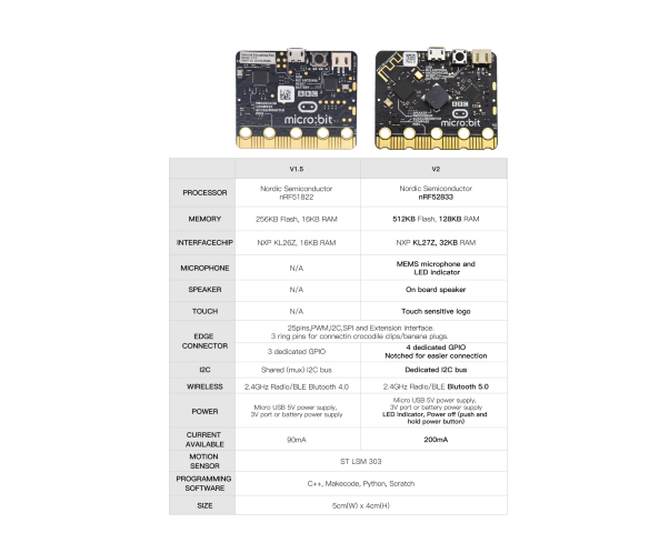
3.2 Comparison between V2.0 & V1.5

Micro:bit main board V2.0

Micro:bit main board V1.5
More details:
For the Micro: Bit main board V2, pressing the Reset & Power button , it will reset the Micro: Bit and rerun the program.If you hold it tight, the red LED will slowly get darker.When the power indicator becomes darker, releasing the button and your Micro: Bit board will enter sleep mode for power saving. This will make your battery more durable. And you could press this button again to ‘wake up’ your Micro:bit.
For more information,please resort to following links:
https://tech.microbit.org/hardware/
https://microbit.org/new-microbit/
https://www.microbit.org/get-started/user-guide/overview/
https://microbit.org/get-started/user-guide/features-in-depth/
3.3 Pinout
Micro:bit main board V2.0 VS V1.5


Browse the official website for more details:
https://tech.microbit.org/hardware/edgeconnector/
https://microbit.org/guide/hardware/pins/
3.4 Notes for the application of Micro:bit main board V2.0
it is recommended to cover it with a silicone protector to prevent short circuit for it has a lot of sophisticated electronic components.
its IO port is very weak in driving since it can merely handle current less than 300mA. Therefore, do not connect it with devices operating in large current,such as servo MG995 and DC motor or it will get burnt. Furthermore, you must figure out the current requirements of the devices before you use them and it is generally recommended to use the board together with a Micro:bit shield.
It is recommended to power the main board via the USB interface or via the battery of 3V. The IO port of this board is 3V, so it does not support sensors of 5V. If you need to connect sensors of 5 V, a Micro: Bit expansion board is required.
When using pins(P3、P4、P6、P7、P10)shared with the LED dot matrix, blocking them from the matrix or the LEDs may display randomly and the data about sensors maybe wrong.
The battery port of 3V cannot be connected with battery more than 3.3V or the main board will be damaged. Forbid to use it on metal products to avoid short circuit.
To put it simple, Micro:bit V2 main board is like a microcomputer which has made programming at our fingertips and enhanced digital innovation. And about programming environment, BBC provides a website: https://microbit.org/code/,which has a graphical MakeCode program easy for use.
4. Install Micro:bit driver
If you have downloaded micro:bit driver, then no need to download it again.
If it is you first time to use micro:bit main board, then you will have to download the driver.
First of all, connect the micro:bit to your computer using a USB cable.
And enter website:
https://www.dropbox.com/sh/w5mv8mvvufti0uj/AADTFPTV8NBN0IxQj_3TZ8ETa?dl=0 to download the driver file of micro:bit
 .
.
5. Getting Started with Micro:bit
The following instructions are applied for Windows system but can also serve as a reference if you are using a different system.
5.1 Write code and program
This chapter describes how to write program with the App Micro: Bit and load the program to the Micro: Bit main board V2.
You are recommended to browse the official website of Micro:bit for more details, and the link is attached below:
https://microbit.org/guide/quick/
Step 1: connect the Micro: Bit main board V2 with your computer
Firstly, link the Micro: Bit main board V2 with your computer via the USB cable.Macs、PCs、 Chromebooks and Linux (including Raspberry Pi)systems are all compatible with the Micro: Bit main board V2.
Note that if you are about to pair the board with your phone or tablet, please refer to this link:
https://microbit.org/get-started/user-guide/mobile/


Secondly, if the red LED on the back of the board is on, that means the board is powered. Then Micro: Bit main board V2 will appear on your computer as a driver named ‘MICROBIT(E:)’. Please note that it is not an ordinary USB disk as shown below.

Step 2: write programs
View the link https://makecode.microbit.org/ in your browser;
Click ‘New Project’;
The dialog box‘Create a Project’ appears, fill it with ‘heartbeat’ and click ‘Create √’ to edit.
(If you are running Windows 10 system, it is also viable to edit on the APP MakeCode for micro:bit , which is exactly like editing in the website. And the link to the APP is https://www.microsoft.com/zh-cn/p/makecode-for-micro-bit/9pjc7sv48lcx?ocid=badgep&rtc=1&activetab=pivot:overviewtab)


Write a set of micro:bit code. You can drag some modules in the Blocks to the editing area and then run your program in Simulator of MakeCode editor as shown in the picture below which demonstrates how to edit ‘heartbeat’ program .
As for loading test code , please turn to Chapter 5.5. And introduction of Makecode is on the next chapter 5.2.

Step 3: download test code
If your computer is Windows 10 and you have downloaded the APP MakeCode for micro:bit to write program, what you will have to do to download the program to your Micro: Bit main board V2 is merely clicking the ‘Download’ button, then all is done.
If you are writing programs through the website, following these steps:
Click the ‘Download’ in the editor to download a “hex” file, which is a compact program format that the Micro: Bit main board can read. Once the hexadecimal file is downloaded, copy it to your board V2 just like the process that you copy the file to the USB driver. If you are running Windows system, you can also right-click and select ‘Send to → MICROBIT (E:) ‘to copy the hex file to the Micro: Bit main board V2.

You can also directly drag the “hex” file onto the MICROBIT (E:) disk.


During the process of copying the downloaded hex file to the Micro: Bit main board V2, the yellow signal light on the back side of the board flashes. When the copy is completed, the yellow signal light will stop flashing and remain on.
Step 4: run the program
After the program is uploaded to the Micro: Bit main board V2, you could still power it via the USB cable or change to via an external power. The 5 x 5 LED dot matrix on the board displays the heartbeat pattern.

Power via micro USB cable

Power via external power(3V)
Step 5:Learn about other programming languages
This chapter has described how to use the Micro: Bit main board V2.
But except for the Makecode graphical programming introduced you can also write Micro: Bit programs in other languages. Go to the link:https://microbit.org/code/ to know about other programming languages , or view the link: https://microbit.org/projects/, to find something you want to have a go.
5.2 Makecode:
Browse https://makecode.microbit.org/ and enter Makecode online editor or open the APP MakeCode for micro:bit of Windows 10.

Click“New Project”, and input“heartbeat”,then enter Makecode editor, as shown below:

There are blocks“on start”and“forever”in the code editing area.
When the power is plugged or reset,“on start”means that the code in the block only executes once, while“forever”implies that the code runs cyclically.
5.3. Quick Download
As mentioned before, if your computer is Windows 10 and you have downloaded the APP MakeCode for micro:bit to write programs, the program written can be quickly downloaded to the Micro: Bit main board V2 by selecting ‘Download’.
While it is a little more trickier if you are using a browser to enter makecode. However, if you use Google Chrome, suitable for Linux,macOS and Windows 10, the process can be quicker too.
We use the webUSB function of Chrome to allow the internet page to access the hardware device connected USB.
You could refer to the following steps to connect and pair devices.
Device pairing:
Connect micro:bit to your computer by USB cable. Click“…”beside“Download”and click“Pair device”.

Then click another“Pair device”as shown below:

Then select ‘’BBC micro:bit CMSIS-DPA” and click “Connect”. If ‘’BBC micro:bit CMSIS-DPA”does not show up for selection, please refer tohttps://makecode.microbit.org/device/usb/webusb/troubleshoot
We also provide  in the resource link https://fs.keyestudio.com/KS4009-4010.
.
What’s more, if you don’t know how to update the firmware of micro:bit, refer to the link:https://microbit.org/guide/firmware/
or browse folder  we provide.

Then click”Download”. The program is directly downloaded to Micro: Bit main board V2 and the sentence “Download completed!”appears.

5.4 Resources and test code
Tools ,test code and other resources can be downloaded via the link: https://fs.keyestudio.com/KS4009-4010 and it contains following files:

5.5 Input test code
We provide hexadecimal code files (project files) for each project.The file contains all the contents of the project and can be imported directly, or you can manually drag the code blocks to complete the program for each project. For simple projects, dragging a block of code to complete the program is recommended. For complex projects, it is recommended to conduct the program by importing the hexadecimal code file we provide.
Let’s take the “Heatbeat” project as an Testto show how to load the code.
Open the Web version of Makecode or the Windows 10 App version of Makecode.

Click “Import File”;


Select“ ../Makecode Code/Project 1_ Heart beat/Project 1_ Heart beat.hex” ;
Then click “Go ahead”.


In addition to importing the test code file provided into the Makecode compiler above, you can also drag the the test code file provided into the code editing area of the Makecode compiler, as shown in the figure below:

After a few seconds, it is done.

Note: if your computer system is Windows7 or 8 instead of Windows 10, the pairing cannot be done via Google Chrome. Therefore, digital signal or analog signal of sensors and modules cannot be shown on the serial port simulator. However, you need to read the corresponding digital signal or analog signal. So what can we do? You can use the CoolTerm software to read the serial port data of the micro:bit. Next chapter is about how to install CoolTerm.
5.6 CoolTerm Installation
CoolTerm program is used to read the data on serial port.
Download CoolTerm program:
https://freeware.the-meiers.org/
After the download, we need to install CoolTerm program file, below is Window system taken as an example.
Choose“win”to download the zip file of CoolTerm
Unzip file and open it. (also suitable for Mac and Linux system)


Double-click  .
.

The functions of each button on the Toolbar are listed below:http://wiki.keyestudio.com/index.php/File:IDE.png

|
Opens up a new Terminal |
|---|---|
|
Opens a saved Connection |
|
Saves the current Connection to disk |
|
Opens the Serial Connection |
|
Closes the Serial Connection |
|
Clears the Received Data |
|
Opens the Connection Options Dialog |
|
Displays the Terminal Data in Hexadecimal Format |
|
Displays the Help Window |


6. Projects
(Note: project 1 to 12 will be conducted with the built-in sensors and LED dot matrix of the Micro:bit main board V2)
Project 1: Heartbeat

( 1 )Project Description
This project is easy to conduct with a micro:bit V2 main board, a Micro USB cable and a computer. The micro:bit LED dot matrix will display a relatively big heart-shaped pattern and then a smaller one. This alternative change of this pattern is like heart beating. This experiment serves as a starter for your entry to the programming world.
( 2 )Components Needed:
Micro:bit main board V2 *1
Micro USB cable*1
( 3)Test Code:
Attach the Micro:bit main board V2 to your computer via the Micro USB cable and begin editing.
Firstly, click”basic”module and find and drag the block “show icon “ to module “forever”;

Secondly, click”basic”module again and find and drag the block “show icon “ to module “forever”and click the little triangle to select “show icon  ”;
”;

Thirdly, click”basic”module and find and drag the block” ”to the code block and click the littler triangle to select 500;
Complete Program:

Note:the “on start”means that blocks in the code are only executed once, “forever”implies that code will run cyclically.
Click”JS JavaScript”, you will find the corresponding programming languages.

Click the little triangle”of JS JavaScript”to choose “Python”, you will find the corresponding Python programming language.

( 4 )Test Results:
After uploading test code to micro:bit main board V2 and keeping the connection with the computer to power the main board, the LED dot matrix shows pattern“ ”and then “
 ”alternatively.
( Please refer to chapter 5.3 to know how to download test code quickly.)
If the downloading is not smooth, please remove the micro USB from the main board and then reconnect them and reopen Makecode to try again.
Project 2: Light A Single LED
( 1 )Project Description:
The LED dot matrix consists of 25 LEDs arranged in a 5 by 5 square. In order to locate these LEDs quickly, as the figure shown below, we can regarded this matrix as a coordinate system and create two aces by marking those in rows from 0 to 4 from top to bottom, and the ones in columns from 0 to 4 from the left to the right. Therefore, the LED sat in the second of the first line is (1,0)and the LED positioned in the fifth of the fourth column is (3,4)and others likewise.

( 2 )Components Needed:
Micro:bit main board V2 *1
Micro USB cable*1
( 3 )Test Code:
Attach the Micro:bit main board V2 to your computer via the Micro USB cable and begin editing.
Firstly, click”Led”module and then the”more”module to find and drag the block “led enable false “ to block“on start”; click the little triangle of “led enable false “ to select”true”;

Secondly, click”Led”module and to find and drag the block “toggle x 0 y 0“ to block“forever”and alter “x0” to”x1”;

Thirdly, click”Basic”module to find and drag the block”pause(ms)100”to “forever” block and set pause to 500;

Fourthly, copy the block  and place it into forever” block;

Fifthly, click”Led”module to find and drag the block”plot x 0 y 0”to “forever” block and change the “x 0 y 0” to “x 3 y 4”;

Sixthly, copy the block “pause(ms)500” and place it into forever” block;

Lastly, click”Led”module to find and drag the block”unplot x 0 y 0”to “forever” block and change “x 0 y 0” to “x 3 y 4”;and copy and place the block“pause(ms)500”to block “forever”;
Complete Program:

Click”JS JavaScript”, you will find the corresponding programming language.

Click the little triangle”of JS JavaScript”to choose “Python”, you will find the corresponding Python programming language.

( 4)Test Results
After uploading test code to micro:bit main board V2 and powering the main board via the USB cable, the LED in (1,0) lights up for 0.5s and the one in (3,4) shines for 0.5s and repeat this sequence.
Project 3: LED Dot Matrix
( 1 )Project Description:
Dot matrices are very commonplace in daily life. They have found wild applications in LED advertisement screens, elevator floor display, bus stop announcement and so on.
The LED dot matrix of Micro: Bit main board V2 contains 25 LEDs in a grid. Previously, we have succeeded in controlling a certain LED to light by integrating its position value into the test code. Supported by the same theory, we can turn on many LEDs at the same time to showcase patterns, digits and characters.
What’s more, we can also click”show icon“ to choose the pattern we like to display. Last but not the least, we can our design patterns buy ourselves.
( 2 )Components Needed:
Micro:bit main board V2 *1
Micro USB cable*1
( 3 )Test Code 1:
Link computer with micro:bit board by micro USB cable, and program in MakeCode editor.
A. Enter“Led”→“more”→“led enable false”
Click the drop-down triangle button to select“true”
Combine it with “on start” block
*****************************************************************
Click“Led”to move“plot x 0 y 0”into“forever”,then replicate“plot x 0 y 0”for 8 times, respectively set to“x 2”y 0”,“x 2”y 1”,“x 2”y 2”,“x 2”y 3”,“x 2”y 4”,“x 1”y 3”“x 0”y 2”,“x 3”y 3”,“x 4”y 2”.

Complete Program:

Select“JavaScript” and“Python”to switch into JavaScript and Python language code:


( 4 )Test Results 1:
Upload code 1 and power on , we will see the icon.
icon.
( 5 ) Test Code 2:
Link computer with micro:bit board by micro USB cable, and program in MakeCode editor.
Enter“Basic”→“show number 0”block.
Duplicate it for 4 times, then separately set to“show number 1”,“show number 2”,“show number 3”,“show number 4”,“show number 5”.

*****************************************************************
Click“Basic”→“show leds”, then put it into“forever”block,tick blue boxes to light LED and generate“↓”pattern.

*****************************************************************
Move out the block“show string” from“Basic”block, and leave it beneath the“show leds” block

Choose“show icon”from“Basic”block, and leave it beneath the block“show string“Hello!”block

*****************************************************************
Enter“Basic”→“show arrow North”;
Leave it into“forever”block,replicate“show arrow North”for 3 times,respectively set to“North East”,“South East”, “South West”,“North West”.

Click“Basic”to get block“clear screen”then remain it below the block “show arrow North West”

*****************************************************************
Drag“pause (ms) 100”block from“Basic”block and set to 500ms, then leave it below“clear screen”block.

Complete Program:

Select“JavaScript” and“Python”to switch into JavaScript and Python language code:


( 6 )Test Results 2:
Upload code 2 and plug micro:bit to power. Micro: bit starts showing number 1, 2, 3, 4, and 5, then cyclically display,“Hello!”, ,
, ,
, ,
, and
and patterns.
Project 4: Programmable Buttons

( 1 )Project Description:
Buttons can be used to control circuits. In an integrated circuit with a button, the circuit is connected when pressing the button and it is open the other way around.
Micro: Bit main board V2 boasts three buttons, two are programmable buttons(marked with A and B), and the one on the other side is a reset button. By pressing the two programmable buttons can input three different signals. We can press button A or B alone or press them together and the LED dot matrix shows A,B and AB respectively. Let’s get started.
( 2 )Components Needed:
Micro:bit main board V2 *1
Micro USB cable*1
( 3 )Test Code 1:
Link computer with micro:bit board by micro USB cable, and program in MakeCode editor.
Delete“on start”and“forever”firstly,then click“Input”→“on button A pressed”
*****************************************************************
Click“Basic”→“show string”;
Then place it into“on button A pressed”block, change “Hello!”into“A”.
Copy code stringonce, tap the drop-down button“A”to select“B”and modify character“A”into“B”.
*****************************************************************
Copyonce,and set to“on button A+B pressed”and“show string “AB”

*****************************************************************
Complete Code:
 Select“JavaScript” and“Python”to switch into JavaScript and Python language code:


( 4 )Test Results 1:
After uploading test code 1 to micro:bit main board V2 and powering the main board via the USB cable, the 5*5 LED dot matrix shows A if button A is pressed, B if button B pressed, and AB if button A and B pressed together.
( 5 ) Test Code 2:
Click“Led”→“more”→“led enable false”,
Put it into the block“on start”,click drop-down triangle button to select“true” .
*****************************************************************
Tap“Variables”→“Make a Variable…”→“New variable name:”
Enter“item”in the dialog box and click“OK”,then variable“item”is produced. And move“set item to 0”into“on start”block

*****************************************************************
Click“Input”→“on button A pressed”.
Go to“Variables”→“ change item by 1 ”
Place it into“on button A pressed”and 1 is modified into 5.
*****************************************************************
Duplicatecode string once,click the drop-down button to select“B”,then set“change item by -5”.
*****************************************************************
Enter“Led”→“plot bar graph of 0 up to 0”
Keep it into“forever”block
Go to“Variables”to move“item”into 0 box,change 0 into 25.

*****************************************************************
Go to“Logic”to move out “if…true…then…”and “=”blocks.
Keep“=”into“true”box and set to “>”.
Select“item”in the“Variables”and lay it down at left box of “>”,change 0 into 25;
D. Enter“Variables”to drag“set item to 0”block into“if…true..then…”, alter 0 into 25.

*****************************************************************
Replicate code string once.
once.
“>” is modified into “<” and 25 is changed into 0, leave it beneath code string.

Complete Program:

Select“JavaScript” and“Python”to switch into JavaScript and Python language code:


( 6 )Test Results 2:
After uploading test code 2 to micro:bit main board V2 and powering the main board via the USB cable, when pressing the button A the LEDs turning red increase while when pressing the button B the LEDs turning red reduce.
Project 5: Temperature Detection

( 1 )Project Description:
Actually ,the Micro:bit main board V2 is not equipped with a temperature sensor, but uses the temperature sensor built into NFR52833 chip for temperature detection. Therefore, the detected temperature is more closer to the temperature of the chip, and there maybe deviation from the ambient temperature.
( 2 )Components Needed:
Micro:bit main board V2 *1
Micro USB cable*
( 3 )Test Code 1:
Click“Advanced”→”Serial”→“serial redirect to USB”into“on start”

*****************************************************************
Go to“Serial”→“serial write value“x”=0”into “forever”

Click“Input” → “temperature(℃)” into“into serial write value“x”=0 and change”0”into “temperature”

*****************************************************************
Go to“Basic”→“pause (ms) 100”into “forever”and set pause to 500

*****************************************************************
Complete Program:

Select“JavaScript” and“Python”to switch into JavaScript and Python language code:


( 4 )Test Results 1:
After uploading test code 1 to micro:bit main board V2, powering the main board via the USB cable, and clicking “Show console Device”, the data of temperature shows in the serial monitor page as shown below.


If you’re running Windows 7 or 8 instead of Windows 10, via Google Chrome won’t be able to match devices. You’ll need to use the CoolTerm serial monitor software to read data.
You could open CoolTerm software, click Options, select SerialPort, set COM port and baud rate to 115200 (after testing, the baud rate of USB SerialPort communication on Micro: Bit main board V2 is 115200), click OK, and Connect. The CoolTerm serial monitor shows the change of temperature in the current environment, as shown in the figures below :


( 5 )Test Code 2:
Link computer with micro:bit board by micro USB cable, and program in MakeCode editor.
Go to“Led”→“more”→“led enable false”block.
Keep it into the“on start”block,tap the triangle button to select“true”.
*****************************************************************
Tap“Logic”and drag“if…then…else”into“forever”block; and then drag “=” into “true”

Enter“Input”to move“temperature(℃)”into the left side of “=”; click the little triangle of “=”to choose “≥”,and change the “0”to “35”

Click“Basic”to find out block“show icon”and move it into“then”; copy and place the block“show icon”to “else”and click the little triangle of “ ”to select “
 ”.
”.

*******************************************************************************
Complete Program:

Select“JavaScript” and“Python”to switch into JavaScript and Python language code:


( 6 )Test Results 2:
After uploading the code 2, when the ambient temperature is less than 35℃, 5*5LED will show . When the temperature is equivalent to or greater than 35℃, the pattern
 will appear.
Project 6: Geomagnetic Sensor

( 1 )Project Description:
This project aims to explain the use of the Micro: bit geomagnetic sensor, which can not only detect the strength of the geomagnetic field, but also be used as a compass to find bearings. It is also an important part of the navigation attitude reference system (AHRS). Micro: Bit main board V2 uses LSM303AGR geomagnetic sensor, and the dynamic range of magnetic field is ±50 gauss. In the board, the magnetometer module is used in both magnetic detection and compass.
In this experiment, the compass will be introduced first, and then the original data of the magnetometer will be checked.The main component of a common compass is a magnetic needle, which can be rotated by the geomagnetic field and point toward the geomagnetic North Pole (which is near the geographic South Pole) to determine direction.
( 2 )Components Needed:
Micro:bit main board V2 *1
Micro USB cable*1
( 3 )Test Code 1:
Link computer with micro:bit board by micro USB cable, and program in MakeCode editor.
Click“Input”→“more”→“calibrate compass”
Lay down it into block“on start”.

Go to“Input”→“on button A pressed”.
Enter“Basic”→“show number”, put it into“on button A pressed”block;
Tap“Input”→“compass heading(℃)”, and place it into“show number”

*****************************************************************
Complete Program:

Select“JavaScript” and“Python”to switch into JavaScript and Python language code:


( 4 )Test Results 1:
After uploading test code to micro:bit main board V2 and powering the board via the USB cable, and pressing the button A, the board asks us to calibrate compass and the LED dot matrix shows “TILT TO FILL SCREEN”. Then enter the calibration page. Rotate the board until all 25 LEDs are all on red as shown below.

After that, a smile pattern appears, which implies the calibration is done. When the calibration process is completed, pressing the button A will make the magnetometer reading display directly on the screen. And the direction north, east, south and west correspond to 0°, 90°, 180° and 270°.
( 5 ) Test Code 2:

This module can keep readings to determine direction, so does point to the current magnetic North Pole by arrow.

For the above picture, the arrow pointing to the upper right when the value ranges from 292.5 to 337.5. 0.5 can’t be input in the code, thereby, the values we get are 293 and 338.
Link computer with micro:bit board by micro USB cable, and program in MakeCode editor.
Enter“Input”→ “more”→“calibrate compass”
Move“calibrate compass”into“on start”
*****************************************************************
Click“Variables”→“Make a Variable…”→“New variable name:”
Input“x”in the blank box and click“OK”, and the variable “x” is generated.
Drag out“set x to”into“forever”block

Go to“Input”→“compass heading(℃)”, and keep it into“0”box.

Tap“Logic”→“if…then…else”, leave it below block“sex x to compass heading”, then click icon for 6 times.
*****************************************************************
A. Place“and”into“true”block
B. Then move“=”block to the left box of “and”
C. Click“Variables”to drag“x”to the left “0”box, change 0 into 293 and set to “≥”;
D. Then copy“x≥293”once and leave it to the right “0”box and set to“x<338”

*****************************************************************
A. Go to“Basic”→“show leds”
B. Lay it down beneath  block, then click“show leds”and the pattern
  appears.

A. Duplicate for 6 times.
B. Separately leave them into the blank boxes behind “else if”.
C. Set to“x≥23 and x<68”,“x≥68 and x<113 ”,“x≥113 and x<158 ”,“x≥158 and x<203 ”,“x≥203 and x<248 ”,“x≥248 and x<293 ”respectively.
D. Then copy “show leds”for 7 times and keep them below the “else if…….then” block respectively.
E. Click the blue boxes to form the pattern“ ”, “
”, “ ”, “
”, “ ”, “
”, “ ”, “
”, “ ”, “
”, “ ”and “
 ”.
”.
*****************************************************************************
Complete Program:


Select“JavaScript” and“Python”to switch into JavaScript and Python language code:


( 6 ) Test Results 2
Upload code 2 and plug micro:bit to power. After calibration, tilt micro:bit board, the LED dot matrix displays the direction signs.
Project 7: Accelerometer
( 1 )Project Description:
The Micro: Bit main board V2 has a built-in LSM303AGR gravity acceleration sensor, also known as accelerometer, with a resolution of 8/10/12 bits. The code section sets the range to 1g, 2g, 4g, and 8g.
We often use accelerometer to detect the status of machines.
In this project, we will introduce how to measure the position of the board with the accelerometer. And then have a look at the original three-axis data output by the accelerometer.
( 2 )Components Needed:
Micro:bit main board V2 *1
Micro USB cable*1
( 3 )Test Code 1:
Link computer with micro:bit board by micro USB cable, and program in MakeCode editor.
(1) A. Enter“Input”→“on shake”.
B. Click“Basic”→“show number”, place it into“on shake”block, then change 0 into 1.

*****************************************************************
(2) A. Copy code string for 7 times.
Separately click the triangle button to select“logo up”,“logo down”,“screen up”,“screen down”,“tilt left”,“tilt right”and“free fall”, then respectively change 1 into 2, 3, 4, 5, 6, 7, 8.
*****************************************************************
Complete Program:


Select“JavaScript” and“Python”to switch into JavaScript and Python language code:


( 4 )Test Results 1:
After uploading the test code 1 to micro:bit main board V2 and powering the board via the USB cable, if we shake the Micro: Bit main board V2. no matter at any direction, the LED dot matrix displays the digit “1”.
When it is kept upright (its logo above the LED dot matrix), the number 2 will show.

When it is kept upside down( its logo below the LED dot matrix) , it will show as below.

When it is placed still on the desk, showing its front side, the number 4 appears.

When it is placed still on the desk, showing its back side, the number 5 will exhibit.
When the board is tilted to the left , the LED dot matrix shows the number 6 as shown below.

When the board is tilted to the right , the LED dot matrix displays the number 7 as shown below

When the board is knocked to the floor, this process can be considered as a free fall and the LED dot matrix shows the number 8. (please note that this test is not recommended for it may damage the main board.)
Attention: if you’d like to try this function, you can also set the acceleration to 3g, 6g or 8g. But still ,we don not recommend.
( 5 )Test Code 2:
A. Go to“Advanced”→“Serial”→“serial redirect to USB”
B. Drag it into“on start”

*****************************************************************
A. Enter“Serial”→“serial write value x =0”
B. Leave it into“forever”block

*****************************************************************
A. Click“Input”→“acceleration(mg) x”;
B. Keep it into“0”box and capitalize the“x”

*****************************************************************
Go to“Basic”and move out“pause (ms) 100”below the block , then set to 100ms.

*****************************************************************
Replicate code string
for 3 times and keep them into“forever”block,separately set the whole code string as follows:

Complete Program:

Select“JavaScript” and“Python”to switch into JavaScript and Python language code:


( 6 ) Test Results 2
Upload test code to micro:bit main board V2, power the main board via the USB cable, and click “Show console Device”.

After referring to the MMA8653FC data manual and the hardware schematic diagram of the Micro: Bit main board V2, the accelerometer coordinate of the Micro: Bit V2 motherboard are shown in the figure below:

The following interface shows the decomposition value of acceleration in X axis, Y axis and Z axis respectively, as well as acceleration synthesis (acceleration synthesis of gravity and other external forces).

If you’re running Windows 7 or 8 instead of Windows 10, via Google Chrome won’t be able to match devices. You’ll need to use the CoolTerm serial monitor software to read data.
You could open CoolTerm software, click Options, select SerialPort, set COM port and baud rate to 115200 (after testing, the baud rate of USB SerialPort communication on Micro: Bit main board V2 is 115200), click OK, and Connect. The CoolTerm serial monitor shows the data of X axis, Y axis and Z axis , as shown in the figures below :

Project 8: Light Detection
( 1 )Project Description:
In this project, we focus on the light detection function of the Micro: Bit main board V2. It is achieved by the LED dot matrix. And it can be viewed as a photosensor.
( 2 )Components Needed:
Micro:bit main board V2 *1
Micro USB cable*1
( 3 )Test Code:
Link computer with micro:bit board by micro USB cable, and program in MakeCode editor.
(1)A. Enter“Advanced”→“Serial”→“serial redirect to USB”;
B. Drag it into“on start”block.
*****************************************************************
(2) A. Go to“Serial”→“serial write value x =0”;
B. Move it into“forever”
A. Click“Input”→“acceleration(mg) x”
B. Put“acceleration(mg) x”in the“0”box and change “x”into“Light intensity”.

*****************************************************************
A. Click“Basic”→“pause (ms) 100”;
B. Lay it down into“forever”and set to 100ms.

*****************************************************************
Complete Program:

Select“JavaScript” and“Python”to switch into JavaScript and Python language code:


( 4 )Test Results:
Upload the test code to micro:bit main board V2, power the board via the USB cable and click “Show console Device”.

When the LED dot matrix is covered by hand, the light intensity showed is approximately 0; when the LED dot matrix is exposed to light,the light intensity displayed gets stronger with the light as shown below.

The 20 in the code is an arbitrary value of light intensity. If the current light level is less than or equal to 20, the moon will appear on the LED dot matrix. If it’s bigger than 20, the sun will appear.
If you’re running Windows 7 or 8 instead of Windows 10, via Google Chrome won’t be able to match devices. You’ll need to use the CoolTerm serial monitor software to read data.
You could open CoolTerm software, click Options, select SerialPort, set COM port and baud rate to 115200 (after testing, the baud rate of USB SerialPort communication on Micro: Bit main board V2 is 115200), click OK, and Connect. The CoolTerm serial monitor shows the value of light intensity, as shown in the figures below :

Project 9: Speaker

( 1 )Project Description:
The Micro: Bit main board V2 has an built-in speaker, which makes adding sound to the programs easier. We can program the speaker to air all kinds of tones .
( 2 )Components Needed:
Micro:bit main board V2 *1
Micro USB cable*1
( 3 )Test Code:
Link computer with micro:bit board by micro USB cable, and program in MakeCode editor.
Enter“Basic”module to find “show icon”and drag it into “on start”block;
Click the little triangle to find “ ”
”

*****************************************************************
Enter“Music”module to find and drug“play sound giggle until done” into “forever”block;
Enter“Basic”module to find and drug“pause(ms) 100” into “forever” block ;
Change 100 into 1000;

Copy  three times and place it into “forever”block ;
Click the little triangle to select “happy”,”hello”,”yawn”;

*****************************************************************
Complete Program:

Select“JavaScript” and“Python”to switch into JavaScript and Python language code:


( 4 )Test Results:
After uploading the test code to micro:bit main board V2 and powering the board via the USB cable, the speaker utters sound and the LED dot matrix shows the logo of music.
Project 10: Touch-sensitive Logo

( 1 )Project Description:
The Micro: Bit main board V2 is equipped with a golden touch-sensitive logo, which can act as an input component and function like an extra button.
It contains a capacitive touch sensor that senses small changes in the electric field when pressed (or touched), just like your phone or tablet screen do. When you press it , you can activate the program.
( 2 )Components Needed:
Micro:bit main board V2 *1
Micro USB cable*1
( 3 )Test Code:
Link computer with micro:bit board by micro USB cable, and program in MakeCode editor.
Delete block“on start”and“forever”;
Enter“Input”module to find and drag“on logo pressed” ;
Click the little triangle to find “touched”’;

Enter module “Variables”→choose“Make a Variable”→input “start”→click “OK”
The variable“start”is established;
Enter“Variables”module to find and drag “set start to 0” into “on logo touched”block;

Enter“Input”module →click “more”→ find and drag“running time(ms)” into the “0”of“set start to 0”block;

Enter“Basic”module to find and drag“show icon” into “on logo touched”block;

Enter“Input”module to find and drag“on logo pressed”→choose “released”→establish variable “time”;
Enter“Variables”module to find and drag “set time to 0”into “on logo pressed”block;
Enter“Math”module to find and drag “0-0”into the “0”of“set start to 0”block;

Enter“Input”module→ “more” → find and drag “running time(ms)” into “0”on the left side of “0-0”;
Enter“Variables”module to find and drag“start” into “0”on the right side of “0-0”;

Enter“Basic”module to find and drag“show number” into “on logo released”block;
Enter“Math”module to find and drag“square root 0” into “0”; Click the little triangle to find”integer÷”;

Enter“Variables”module to find and drag“time” into “0”on the left side of “0-0”and change the “0”on the right side to”1000”;

Complete Program:

Select“JavaScript” and“Python”to switch into JavaScript and Python language code:


( 4 )Test Results:
After uploading the test code to micro:bit main board V2 and powering the board via the USB cable, the LED dot matrix exhibits the heart pattern when the touch-sensitive logo is pressed or touched and displays digit when the logo is released.
Project 11: Microphone


( 1 )Project Description:
The Micro: Bit main board V2 is built with a microphone which can test the volume of ambient environment. When you clap, the microphone LED indicator will turn on. Since it can measure the intensity of sound, you can make a noise scale or disco lighting changing with music. The microphone is placed on the opposite side of the microphone LED indicator and in proximity with holes that lets sound pass.When the board detects sound, the LED indicator lights up.
( 2 )Components Needed:
Micro:bit main board V2 *1
Micro USB cable*1
( 3 )Test Code 1:
Link computer with micro:bit board by micro USB cable, and program in MakeCode editor.
( 1 ) Delete block“on start”and“forever”;
( 2 ) Enter“Input”module to find and drag“on loud sound”;
Enter“Basic”module to find and drag “show number”into “on loud sound”block ;

( 3 )Copy  once;
once;
Click the little triangle of “lond” to choose”quiet”;
Click the little triangle of “” to choose” ”;
”;

Complete Program:

Select“JavaScript” and“Python”to switch into JavaScript and Python language code:


( 4 )Test Results 1:
After uploading test code to micro:bit main board V2 and powering the board via the USB cable, the LED dot matrix displays pattern “”when you claps and pattern when it is quiet around.
( 5 )Test Code 2:
Link computer with micro:bit board by micro USB cable, and program in MakeCode editor.
Enter“Advanced”module→ choose“Serial”to find and drag“serial redirect to USB” into “on start”block ;
Enter“Variables”module→ choose“Make a Variable”→ input “maxSound”→click “OK”,variable ”maxSound”is established;
Enter“Variables”module to find and drag“set maxSound to 0”into “on start”block ;

Enter“Logic”module to find and drag“if true then…else”into “forever”block ;
Enter“Input”module to find and dragbutton A is pressed”into “then” ;

Enter“Basic”module to find and drag“show number”into “then” ;
Enter“Variables”module to find and drag“maxSound”into “0” ;

Establish variable“soundLevel”;
Enter“Variables”module to find and drag“set soundLevel to 0”into “else”;
Enter“Input”module to find and drag“sound level” into “0”;

Enter“Led”module to find and drag“plot bar graph of 0 up to 0” into “else”;
Enter“Variables”module to find and drag“soundLevel”into the“0”behind “of”;
Change the “0”behind “up” to “255”;

Enter“Logic”module to find and drag“if true then”into “else”block ;
Enter“Logic”module to find and drag“0 > 0”into “then” ;
Enter“Variables”module to find and drag“soundLevel”into “0”on the left side of “0-0” ;
Enter“Variables”module to find and drag“maxSound” into “0” on the right side;

Enter“Variables”module to find and drag“set maxSound to 0”into the second “then”;
Enter“Variables”module to find and drag“soundLevel”into the “0” ;

Complete Program:

Select“JavaScript” and“Python”to switch into JavaScript and Python language code:


( 6 )Test Results 2:
Upload test code to micro:bit main board V2, power the board via the USB cable and click “Show console Device”as shown below.

When the sound is louder around, the sound value shows in the serial port is bigger as shown below.

What’s more, when pressing the button A, the LED dot matrix displays the value of the biggest volume( please note that the biggest volume can be reset via the Reset button on the other side of the board ) while when clapping, the LED dot matrix shows the pattern of the sound.
Project 12: Bluetooth Wireless Communication

( 1 )Project Description:
The Micro: Bit main board V2 comes with a nRF52833 processor (with built-in Bluetooth 5.1 BLE(Bluetooth Low Energy) device) and a 2.4GHz antenna for Bluetooth wireless communication and 2.4GHz wireless communication. With the help of them, the board is able to communicate with a variety of Bluetooth devices, including smart phones and tablets.
In this project, we mainly concentrate on the Bluetooth wireless communication function of this main board. Linked with Bluetooth, it can transmit code or signals. To this end, we should connect an Apple device (a phone or an iPad) to the board.
Since setting up Android phones to achieve wireless transmission is similar to that of Apple devices, no need to illustrate again.
( 2 ) Preparation
Attach the Micro:bit main board V2 to your computer via the Micro USB cable.
An Apple device (a phone or an iPad) or an Android device;
( 3 ) Procedures:
For Apple devices, enter this link https://www.microbit.org/get-started/user-guide/ble-ios/ with your computer first, and then click “Download pairing HEX file”to download the Micro: Bit firmware to a folder or desk, and upload the downloaded firmware to the Micro: Bit main board V2.


Search “micro bit”in your App Store to download the APP micro:bit.

Connect your Apple device with Micro: Bit main board V2:
Firstly, turn on the Bluetooth of your Apple device and open the APP micro:bit to select item “Choose micro:bit”to start pairing Bluetooth.
Please make sure that the Micro: Bit main board V2 and your computer are still linked via the USB cable.

Secondly, click “Pair a new micro:bit”;

Following the instructions to press button A and B at the same time(do not release them until you are told to) and press Reset & Power button for a few seconds.
Release the Reset & Power button, you will see a password pattern shows on the LED dot matrix. Now , release buttons A and B and click Next.


Set the password pattern on your Apple device as the same pattern showed on the matrix and click Next.

Still click Next and a dialog box props up as shown below. Then click “Pair”. A few seconds later, the match is done and the LED dot matrix displays the “√” pattern.


After the match with Bluetooth, write and upload code with the App.
Click “Create Code” to enter the programming page and write code.
Click  and the box
  appears, and then select “Create √”.


Name the code as “1 “and click  to save it.

Click the third item“Flash”to enter the uploading page. The default code program for uploading is the one saved just now and named “1” and then click the other “Flash” to upload the code program “1”.


If the code is uploaded successfully a few seconds later, the App will emerge as below and the LED dot matrix of the Micro: Bit main board V2 will exhibit a heart pattern.

Note: G , - and GND marked on sensors/modules denote negative poles, which are connected to the G ports of V2 shield ; V, + and VCC indicate the positive electrodes, which are linked with the V1 or V2 ports of V2 shield.
Project 13: Hello world!
Overview
This project is very simple. A micro:bit could display“Hello World!”through a USB cable. This is also an entry experiment for you to enter the programming world of micro bit.
In the experiment, we will serve CoolTerm program as a serial communication software.
Components Required:
Micro:bit main board*1
USB cable*1
Test Code

Test Results
Connect micro:bit to computer via USB cable and transfer code to micro:bit.
Open CoolTerm, click Options and select SerialPort, set COM port and baud rate(115200). Click OK and Connect.
Tap“Capslock”to set to capital mode and press“R”on keyboard, as a result, “ Hello World!”will be displayed as below:

Project 14: LED Blinks
Overview
The LED blink is one of the more basic experiments. In the above Testuse of micro:bit, we have mentioned the 25 LED display of micro:bit. In this project, you will learn how to control an LED blink using a keyestudio digital white LED module and micro:bit sensor shield. Before testing, you should first turn off the 5*5 LED function of micro:bit.
Components Required:
Micro:bit main board*1
Keyestudio Micro bit sensor V2 shield*1
USB Cable*1
Keyestudio Digital White LED Module*1
Dupont jumper wire*3
6-Slot AA Premium Battery Holder*1
1.5V AA Battery*6
Component Introduction
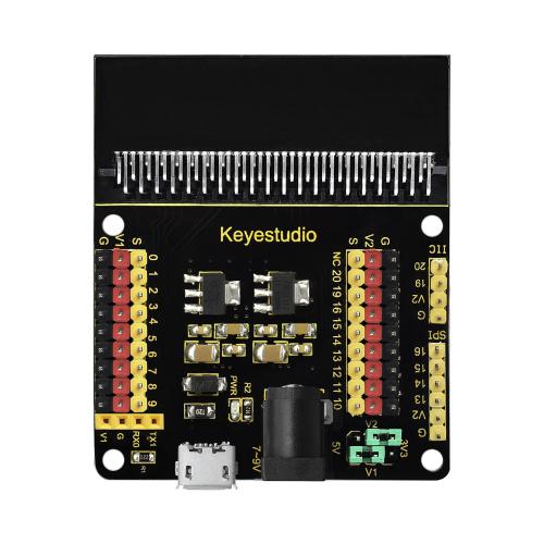
Keyestudio Micro bit Sensor V2 Shield:
This shield is very easy for micro:bit wiring. It breaks out the PI0 ports in the form of 3Pin (GND, VCC, PI0), easy to connect other sensor modules. Also with communication interfaces, like serial port、I2C and SPI pin headers.
You can power the shield via USB connection or external DC power jack (DC7-9V). If power the sensor module, you can control it via two cap V1 and V2 on the shield, with DC3.3V and 5V.
Power the sensor shield with DC 7-9V, and this shield can power the micro:bit and other sensor modules, pretty convenient.
Special note: when connect external sensor module to the shield for working, the operating current of AMS1117-3.3V and NCP1117ST50T3G chip is too large, so it is easy to get hot. Pay special attention to avoid touching the two chips and causing burns.

Test Code

Test Results
Done wiring and powered up, send the code to micro:bit, you will see an LED blink on the module, with an interval about one second.
Project 15: Breathing Effect
Overview
The light breath experiment is a little bit similar to the previous project. This time we connect the keyestudio LED module to the sensor shield. Connect the Signal pin of LED module to P0 of micro:bit. From the Pinout diagram of micro:bit, you can get the P0 can be used as Analog IN.
This lesson you will learn how to control the brightness of LED on the module, gradually becoming brighter and dimming, just like the LED is breathing.
Component Required:
Micro:bit main board*1
Keyestudio Micro bit Sensor V2 Shield*1
USB Cable*1
keyestudio Digital Red LED Module*1
Dupont jumper wire*3
Premium Battery Holder 6-cell AA*1
1.5V AA Battery*6
Component Introduction
Keyestudio Digital Red LED Module:
This keyestudio digital red LED module has 3 Pins; - pin is connected to ground, + pin is connected to VCC(3.3-5V), S pin is for signal control; you can set the High or Low level to control the LED on and off.
Connection Diagram

Test Code

Test Results
Done wiring and powered up, send the code to micro:bit, you should finally see an LED on the module gradually become brighter, then gradually dim, circularly just like the LED is breathing.
Project 16: LED Blinks and Breathes
Overview
In this project, we combine the project 2 and project 3. You will learn how to control the LED on the module blink for twice, then breath for twice, circularly. This time we use keyestudio 3W LED module, which has high brightness and can be used as illumination.
Components Required:
Micro:bit main board*1
Keyestudio Micro bit Sensor V2 Shield*1
USB Cable*1
Keyestudio 3W LED Module*1
DuPont jumper wires
Premium Battery Holder 6-cell AA*1
1.5V AA Battery*6

Component Introduction
Keyestudio 3W LED Module:
This LED module is of high brightness because the lamp beads it carries is3w. You can apply this module to Arduino or other projects, ideal for Robot or search and rescue application. For example, intelligent robots can use this module for illumination purpose. Please note that the LED light can’t be exposed directly to human eyes for safety concerns.
Connection Diagram

Test Code

Test Results
Done wiring and powered up, send the code to micro:bit, you should see the LED on the module firstly blink twice, then breath twice, circularly.
Project 17: Make A Sound
Overview
In this project, you will learn how to generate a sound with keyestudio digital active buzzer module. Here you can refer to LED blink, in this lesson control the buzzer on and off circularly.
Component Introduction
Keyestudio Digital Buzzer Module:
It is the simplest sound making module. You can use High/Low level to drive it. Changing the frequency it buzzes can produce different sounds.
Buzzers can be categorized as active and passive ones. The difference between the two is that an active buzzer has a built-in oscillating source, so it will generate a sound when electrified. The buzzer on this module is an active buzzer. This module is widely used in our daily appliances like PC, refrigerator, telephones, timers and other electronic products for voice devices. etc.
Component Required:
Micro:bit main board*1
Keyestudio Micro bit Sensor V2 Shield*1
USB Cable*1
keyestudio Digital Buzzer Module*1
Dupont jumper wire*3
Premium Battery Holder 6-cell AA*1
1.5V AA Battery*6
Connection Diagram

Test Code

Test Results
Done wiring and powered up, send the code to micro:bit, you should hear the buzzer module sound and then stop, circularly. It seems like the sound is interrupted.
Project 18: Play Music
Overview
In this project, you will learn how to play music with keyestudio passive buzzer module. We are going to complete two experiments.
One is to directly control the High and Low level input of micro:bit P0 end, set two square waves to control the buzzer sound. The other is to use the software’s own function, input the square waves of different frequencies and different lengths on the P0 end. Finally make the buzzer module play the song “Ode to Joy”. (The input PIO port can only be P0, can not be other interfaces).
Component Required:
Micro:bit main board*1
Keyestudio Micro bit Sensor V2 Shield*1
USB Cable*1
keyestudio Passive Buzzer Module*1
Dupont jumper wire*3
Premium Battery Holder 6-cell AA*1
1.5V AA Battery*6
Passive Buzzer Module:

Buzzers can be categorized as active and passive ones. The difference between the two is that an active buzzer has a built-in oscillating source, so it will generate a sound when electrified. The buzzer used on this module is a passive buzzer. A passive buzzer does not have such a source, so DC signal cannot drive it beep. Instead, you need to use square waves whose frequency is between 2K and 5K to drive it. Different frequencies produce different sounds. You can use micro:bit to code the melody of a song, quite fun and simple.
Connection Diagram

Test Code
Program 1:

Program 2:


Note: on the MakeCode Block webpage, click the icon , you can see the frequency of each tone as follows.

Test Results
Done wiring and powered up, send the code 1 to micro:bit, you should hear two sounds produced from passive buzzer circularly. If send the code 2 to micro:bit, the buzzer will play the song Ode To Joy! Really amazing. Right? You can try to change the tone to play other music.
Project 19: Change Colors
Overview
In this project, we will use a keyestudio RGB LED module. This Common Anode RGB LED module is a fun and easy way to add some color to your projects. In our program, we will connect the RGB module to micro:bit, then control the P0, P1, P2 Analog Input of micro:bit main board. You will learn how to control the RGB LED on the module firstly show three colors (Red, Green and Blue), then quickly change the color state.
Component Required:
Micro:bit main board*1
Keyestudio Micro bit Sensor V2 Shield*1
USB Cable*1
keyestudio RGB LED Module*1
DuPont jumper wire*4
Premium Battery Holder 6-cell AA*1
1.5V AA Battery*6
RGB LED Module:
RGB comes from the initials of three additive primary colors, red, green, and blue. RGB LEDs are like 3 regular LEDs in one, how to use and connect them is not much different. They come mostly in 2 versions: Common Anode or Common Cathode. Common Anode uses 5V on the common pin, while Common Cathode connects to ground.
This keyestudio RGB LED module is Common Anode. It can be seen as separate LEDs. LEDs have three different color-emitting diodes that can combined to create all sorts of colors. This RGB LED module is very easy for wiring, with a fixed hole that you can mount it on your any devices.
Connection Diagram

Test Code

Test Results
Done wiring and powered up, send the code to micro:bit, you should see the RGB module firstly show three colors, separately red, green and blue light. Then change the color quickly and circularly.
Project 20: Button Control
Overview
When design the circuit, button switch is a commonly used component. The micro:bit main board has two built-in buttons, however, sometimes still need to use external button when design the circuit. So in this project, you will learn how to use our push button module to control 5*5 LED of micro:bit display different images.
Component Required:
Micro:bit main board*1
Keyestudio Micro bit Sensor V2 Shield*1
USB Cable*1
keyestudio Digital Push Button*1
keyestudio Digital White LED Module*1
DuPont jumper wire*6
Premium Battery Holder 6-cell AA*1
1.5V AA Battery*6
Component Introduction
Digital Push Button Module:

The buttons are common input devices. You will have used a power button to switch off the mobile or tablet, or volume buttons to turn the audio level up or down. The buttons on the BBC micro:bit are input devices that can be pressed to trigger an action. You can write a program to tell the micro:bit what actions should happen when the button is pressed, and there are lots of you can program. There are two buttons on the micro:bit, button A and button B. The button can be pressed separately or together. There is a third button on the other side, that’s for resetting your micro:bit and start your program from the beginning.
Connection Diagram

Test Code

Test Results
Wire up according to connection diagram, connect to external power, upload code to micro:bit, press button and LED is on; when button is released, LED is off.
Project 21: Tilt Control
Overview
When design the circuit, sometimes you will need to test whether an object is tilted left or right, so in this case you can use our tilt sensor. In this project, you will learn how to use our digital tilt sensor to control 5*5 LED of micro:bit display different images.
Component Required:
Micro:bit main board*1
Keyestudio Micro bit Sensor V2 Shield*1
USB Cable*1
Keyestudio Digital Tilt Sensor*1
DuPont jumper wire*3
Premium Battery Holder 6-cell AA*1
1.5V AA Battery*6
Component Introduction
Tilt Sensor:
This keystudio digital tilt sensor mainly integrates a tilt sensor. The tilt sensor is a component that can detect the tilting of an object.
The principle is very simple. It mainly uses the ball in the switch changing with different angle of inclination to achieve the purpose of triggering circuits. When the ball in tilt switch runs from one end to the other end because of external force shaking, the tilt switch will conduct, or it will break.
Connection Diagram

Test Code

Test Results
Done wiring and powered up, send the code to micro:bit. When tilt the sensor to the left, you should see the LED matrix of micro:bit show the icon like a heart . If tilted to the right, it will show the icon like this
  .
.
Project 22: Light Interrupter
Overview
In daily life, we often need to implement the function of counting and speed measurement. How to achieve these functions? You can easily match photo-interrupter module with microcontroller via code debugging.
A Photo interrupter is a transmission-type photosensor, which typically consists of a light emitting elements and light receiving elements aligned facing each other in a single package, that works by detecting light blockage when a target object comes between both elements. We could finish counting and speed detection by observing the change of the signals end on module.
In this lesson, we connect a keyestudio photo-interrupter module to micro:bit sensor shield, then control 5*5 LED of micro:bit show different images and red LED.
Component Required:
Micro:bit main board*1
Keyestudio Micro bit Sensor V2 Shield*1
USB Cable*1
Keyestudio Photo Interrupter Module*1
Keyestudio Digital Red LED Module*1
DuPont jumper wire*6
Premium Battery Holder 6-cell AA*1
1.5V AA Battery*6
Connection Diagram

Test Code


Test Results
Done wiring and powered up, send the code to micro:bit. When cover the notch of sensor with a piece of paper, you will view number 1 is shown on micro:bit and LED will light up; on the contrary, micro:bit will display 0 and LED will be off.
Project 23: Capacitive Touch
Overview
In the above project 8, we have done a button control experiment. This time, we are going to replace the button switch with a capacitive touch sensor. In this project, you will learn how to use Keyestudio touch sensor to control active buzzer.
Component Required:
Micro:bit main board*1
Keyestudio Micro bit Sensor V2 Shield*1
USB Cable*1
keyestudio Capacitive Touch Sensor*1
keyestudio Digital Buzzer Module*1
DuPont jumper wire*6
Premium Battery Holder 6-cell AA*1
1.5V AA Battery*6
Component Introduction
Capacitive Touch Sensor:
The module is based on a touch detection IC. This module allows you to remove the troubles of conventional push-type buttons. It has low power consumption and wide working voltage.
Powered on, the module requires the stable time about 0.5sec, at the moment all functions are banned to conduct self-calibration, do not touch the key, the calibration cycle is about 4.0sec.
It can be applied to the waterproof electrical, button replacement, etc.
Connection Diagram

Test Code


Test Results
Done wiring and powered up, transfer code to micro:bit. When touch the sensing area of sensor, the active buzzer will emit sound, conversely , it won’t make a sound.
Project 24: Traffic Light
Overview
When walking at the crossroad, you can see the traffic light command the orderly movement of pedestrians and vehicles. So how is the traffic light controlled to operate? In this project, we will connect a traffic light module to our sensor shield, controlling traffic light blink with micro:bit. You will learn how to simulate the running of traffic light.
Component Introduction
Traffic Light Module:
When learning the microcontroller, you may usually use three separate LEDs (red, green and yellow) to simulate the traffic light blinking. In this way you may need more wire connection. We specially design this traffic light module, which is very convenient for wiring. It has integrated three LEDs (red, green and yellow) together on the module. Also breaks out four pin interfaces. There are two positioning holes for easy installation.
Component Required:
Micro:bit main board *1
Keyestudio Micro bit Sensor V2 Shield *1
USB Cable *1
Keyestudio Traffic Light Module *1
DuPont jumper wire *4
Premium Battery Holder 6-cell AA*1
1.5V AA Battery*6
Connection Diagram

Test Code

Test Results
Done wiring and powered up, send the code to micro:bit, eventually you should see the green LED lights 5 seconds then off, and yellow LED starts to blink 3 times with an interval of 0.5 second, then off, followed by red LED lights up for 5 seconds then off. Up to this moment, green LED lights again, forming a loop cycle.
Project 25: Magnetic Detection
Overview
In this project, you will learn how to use our hall magnetic sensor to control 5*5 LED of micro:bit display different images.
Component Introduction
Hall Magnetic Sensor:
The main component used in this sensor is A3144E. This hall magnetic sensor can be used to detect a magnetic field, outputting Digital signal. It can sense the magnetic materials within a detection range up to 3cm.
Note that it can only detect whether exists a magnetic field nearby but can not detect the strength of magnetic field.
Component Required:
Micro:bit main board*1
Keyestudio Micro bit Sensor V2 Shield*1
USB Cable*1
keyestudio Hall Magnetic Sensor*1
Dupont jumper wire*3
Premium Battery Holder 6-cell AA*1
1.5V AA Battery*6
Connection Diagram

Test Code

Test Results
Done wiring and powered up, send the code to micro:bit. You can place a magnetic bead near the sensor.
When hall sensor doesn’t detect the magnetic field around, you should see the LED matrix of micro:bit show the icon like a heart . Or else, it will show the icon like this
 .
.
Project 26: Follow Black Line
Overview
When doing DIY experiments, you perhaps see such a smart car that can follow a black line and not beyond the black area. How can achieve this? Yeah, make use of line tracking sensors. In this project, we will use a tracking sensor combined with micro:bit to detect an object or a black line. You can get the result shown on the LED display of micro:bit.
Component Required:
Micro:bit main board*1
Keyestudio Micro bit Sensor V2 Shield*1
USB Cable*1
keyestudio Line Tracking Sensor*1
DuPont jumper wire*3
Premium Battery Holder 6-cell AA*1
1.5V AA Battery*6
Component Introduction
Line Tracking Sensor:
The tracking sensor is actually an infrared sensor, which can detect a black line. The component used in the sensor is TCRT5000 infrared tube.
Its working principle is to use the different reflectivity of infrared light to the color, then convert the strength of the reflected signal into a current signal.
When sensor detects a black line, the infrared rays are not emitted or the intensity of emitted ray back are not sufficiently strong, so that the sensor’s signal terminal outputs a High level. Otherwise, output a Low level.
In this way, we can judge the detected color by High or Low level of the sensor’s signal terminal.
Note: on the module, you can rotate the potentiometer to make the LED between on and off state. The sensitivity is the best.
Connection Diagram

Test Code

Test Results
Done wiring and powered up, send the code to micro:bit. When sensor detects no object or detects a black line, the infrared rays are not emitted or the intensity of emitted ray back are not sufficiently strong, so that the sensor’s signal terminal will output a High level, LED on the micro:bit will show the number 1. Or else show the number 0.
Note: rotate the potentiometer on the sensor, the sensitivity is highest when make the LED on and off state. The detection height is 0—3 cm.
Project 27: Obstacle Avoidance
Overview
When doing DIY experiments, you perhaps see such a smart car that can automatically avoid an obstacle ahead. How can achieve this? Yeah, make use of infrared obstacle avoidance sensors. In this project, we will use a obstacle sensor combined with micro:bit to detect an object ahead and automatically avoid it. You can get the result shown on the LED display of micro:bit.
Component Introduction
Obstacle Avoidance Sensor:
The infrared obstacle detector sensor is actually a distance-adjustable obstacle avoidance sensor.
It has a pair of infrared transmitting and receiving tubes. The transmitter emits an infrared ray of a certain frequency. When the detection direction encounters an obstacle (reflecting surface), the infrared rays are reflected back, and receiving tube will receive it. At this time, the signal terminal will output Low level.
If no obstacle detected, the infrared ray emitted is weakened by the distance it travels and eventually disappears, so receiving tube cannot receive it and signal end of sensor will output High level.
In this case, it can judge whether there is an obstacle ahead or not.
You can rotate the potentiometer knob on the sensor to adjust the detection distance. The effective distance is 2-40cm and working voltage is 3.3V-5V.
Component Required:
Micro:bit main board*1
Keyestudio Micro bit Sensor V2 Shield*1
USB Cable*1
keyestudio Obstacle Detector Sensor*1
DuPont jumper wire*3
Premium Battery Holder 6-cell AA*1
1.5V AA Battery*6
Connection Diagram:

Test Code:

Test Results
Done wiring and powered up, send the code to micro:bit. When sensor detects an object ahead, its signal terminal will output a Low level, and LED matrix on the micro:bit will show the number 0. Or else show the number 1.
Note: for obstacle sensor, you can rotate the two potentiometers on the sensor to adjust its sensitivity. Rotate the potentiometer near the infrared transmitter tube clockwise to the end, and then adjust the potentiometer near the infrared receiver. Sled light is turned off and keeps the critical point to be lit. The sensing distance is the longest.
The effective distance of the sensor is within 2-40 cm.
Project 28: Someone Comes
Overview
You may see such a lens in a film or television. When someone wants to attack a target, but not close to the target, they were directly found and the alarm sounded. When some special forces go to the target, they will be covered with moist mud, so that they will not be discovered by the other party. Why ?
Originally, the human body will emit a certain wavelength of infrared rays of about 10um. The relevant sensors are installed near the targets that are being attacked to sense the infrared rays emitted by the human body and then alarm. After the mud is applied, the sensors can not sense the infrared rays emitted by the human body.
In this project, you will learn how to use a PIR motion sensor and micro:bit to detect whether there is someone move nearby. Finally show the different images on 25 LED matrix of micro:bit.
Component Introduction
PIR Motion Sensor:
This sensor can detect infrared signals from a moving person or moving animal nearby, and output High level at signal end. If no detected, output Low level. Note that it can only detect the moving human body, do not detect the body in static. And the detection distance is 3m at most.
Components Required:
Micro:bit main board*1
Keyestudio Micro bit Sensor V2 Shield*1
USB Cable*1
Keyestudio PIR Motion Sensor*1
Keyestudio Digital Buzzer Module*1
DuPont jumper wire*6
Premium Battery Holder 6-cell AA*1
1.5V AA Battery*6
Connection Diagram

Test Code

Test Results
Done wiring and powered up, send the code to micro:bit. When sensor detects the movement of someone nearby, active buzzer will make a sound and micro:bit will show“ ”; otherwise, micro:bit will show “❤”and no sound emits.
Project 29: Fire Alarm
Overview
In daily life, it is often seen that a fire broke out without any precaution. It will cause great economic and human loss. So how can we avoid this situation? Right, install a flame sensor and a speaker in those places that easily break out a fire. When the flame sensor detects a fire, the speaker will alarm people quickly to put out the fire.
So in this project, you will learn how to use a flame sensor and an active buzzer module to simulate the fire alarm system.

Component Introduction
Flame Sensor:
This flame sensor can be used to detect fire or other light sources with wavelength stands at 760nm ~ 1100nm. Its detection angle is about 60°. You can rotate the potentiometer on the sensor to control its sensitivity. Adjust the potentiometer to make the LED at the critical point between on and off state. The sensitivity is the best.
In the fire-fighting robot game, the flame sensor plays an important role in probing the fire source.
Component Required:
Micro:bit main board*1
Keyestudio Micro bit Sensor V2 Shield*1
USB Cable*1
Keyestudio Flame Sensor*1
Keyestudio Digital Buzzer Module*1
DuPont jumper wire* 6
Premium 6-Slot AA Battery Holder *1
1.5V AA Battery*6
Connection Diagram

Test Code


Test Results
Done wiring and powered up, send the code to micro:bit. When flame sensor detects the fire nearby, the buzzer module will sound immediately,and micro”bit will display “0”; If no fire is detected, the buzzer doesn’t beep, number 1 will be shown on micro:bit.
Project 30: To the Top
Overview
During the DIY, we may usually use a machine-3D printer. You can use it to print any elements with different structures. And limit switch is essential in the printing, which mainly provides the information whether XYZ axis of printer reach the boundary point.
Keyestudio crash sensor is a limit switch, available for 3D printer. It is in essence the same as button module. When printer reaches the top to crash the spring plate of module, module outputs Low level. If loosen the spring plate, module outputs High.
In this lesson, you will learn how to use a collision sensor and a digital buzzer module to simulate the 3D printer limit.
Component Introduction
Crash Sensor:
Crash sensor, also known as electronic switch, is a digital on-off input module. The features are as follows:
1. When collision happens upfront of where crash module is installed, module outputs low level signal; no collision, outputs high level signal.
2. With a mounting hole, convenient for fixation on any devices.
3. PCB size: 3.1cm * 2.1cm
4. With switch indicator light, if there is collision, LED on; if no collision, LED off.
Component Required:
Micro:bit main board*1
Keyestudio Micro bit Sensor V2 Shield*1
USB Cable*1
keyestudio Crash Sensor*1
keyestudio Digital Buzzer Module*1
DuPont jumper wire*6
Premium Battery Holder 6-cell AA*1
1.5V AA Battery*6
Connection Diagram

Test Code


Test Results
Done wiring and powered up, send the code to micro:bit. When the spring plate of crash sensor is pressed, the buzzer module will beep, otherwise buzzer will not sound.
Project 31: Magnetic Switch
Overview
In this project, you will learn how to use a keyestudio reed switch module and micro:bit to detect the magnetic field. Finally show the result on the 25 LED matrix of micro:bit. Actually in the project 13, we have used a hall magnetic sensor to detect whether there is magnetic field nearby. So what is the differences between hall magnetic sensor and reed switch module? You can check it in component introduction below.
Component Introduction
Reed Switch Module:
The keyestudio reed switch module is mainly composed of a reed switch. The reed switch is a mechanical magnetic switch, a passive device. Its working principle is that the magnetic field magnetizes its reed, so that it can be turned on and off to achieve the switch effect. However, since it is a contact type switch, its working life is limited, and it is easy to be damaged during transportation and installation.
The main component used in keyestudio Hall Magnetic Sensor is the A3144E, which is an electronic magnetic device, active device. And the output form is a switch type. It uses magnetic fields and Hall effects for contactless control purposes. Since the Hall element itself is a chip, its working life is theoretically unlimited.
Reed switch has been widely applied in household appliances, cars, communication, industry, health care and security areas.
Furthermore, it can also be applied to other sensors and electric devices such as liquidometer, door magnet, reed relay and more.
Component Required:
Micro:bit main board*1
Keyestudio Micro bit Sensor V2 Shield*1
USB Cable*1
keyestudio Reed Switch Module*1
keyestudio Digital Red LED Module*1
DuPont jumper wire*6
Premium Battery Holder 6-cell AA*1
1.5V AA Battery*6
Connection Diagram

Test Code


Test Results
Done wiring and powered up, send the code to micro:bit. When the reed sensor detects a magnetic field nearby, you will view the micro:bit show “0” and red LED turns on, otherwise, “1” is shown on micro:bit and LED is off.
Project 32: Relay Module
Overview
In daily life, we generally use 220V AC to drive the electrical equipment. Sometimes we will use the switch to control the electrical appliance. If directly connect the switch to the 220V AC circuit, once electric leakage happened, people are in danger. Considered with safety, we particularly design this keyestudio single relay with terminal block of NO (normally open) and NC(normally closed), which is active at High.
In this project, you will learn how to use our relay module and micro:bit to control an LED module on and off. (note that for easy wiring, the circuit does not add 220V voltage, still use 5V.)
Component Introduction
Single Relay Module:
This module uses a high-quality SONGLE 5V relay. The relay output is by a light-emitting diode, can be controlled through digital IO. It can be used to control lighting, electrical and other devices of high current or voltage.
When supply high voltage to S end, the relay is driven, that is, normally open(NO) connected, normally closed (NC) disconnected.
When supply low voltage to S end, the relay is turned off, that is, NO is disconnected, and NC connected.
In this way, we connect the 220V AC circuit to NO or NC terminal block, more safe and convenient through 5V voltage control.
Components Required:
Micro:bit main board*1
Keyestudio Micro bit Sensor V2 Shield*1
USB Cable*1
keyestudio Single Relay Module*1
DuPont jumper wire*3
Premium Battery Holder 6-cell AA*1
1.5V AA Battery*6
Connection Diagram

Test Code

Test Results
Done wiring and plug in power, transfer the code to micro:bit, the relay module is connected, after 1s, it is disconnected, with an interval of one second, repeatedly.
Project 33: Ultrasonic Ranging
Overview
Ultrasonic sensor is great for all kind of projects that need distance measurements, avoiding obstacles as examples.
In this project, you will learn how to use a ultrasonic module and micro:bit to detect the distance between the module and an obstacle ahead.
Component Introduction
Ultrasonic Module:
This Ultrasonic detector module HC-SR04 can provide 2cm-450cm non-contact measurement distance, and its ranging accuracy is up to 3mm. It includes an ultrasonic transmitter, receiver and control circuit.
Ultrasonic module will emit the ultrasonic waves after trigger signal. When the ultrasonic waves encounter an object and are reflected back, the module outputs an echo signal, so it can determine the distance of object from the time difference between trigger signal and echo signal.
The basic principle of work as follows:

First pull down the TRIG, and then trigger it with at least 10us high level signal;
After triggering, the module will automatically transmit eight 40KHZ square waves, and automatically detect whether there is a pulse signal back.
If there is a signal back, through the ECHO to output a high level, the duration time of high level is actually the time from sending ultrasonic to returning back.
Test distance = high level duration * velocity of sound (340m/s) * 0.5
Component Required:
Micro:bit main board*1
Keyestudio Micro bit Sensor V2 Shield*1
USB Cable*1
keyestudio Ultrasonic Module*1
Dupont jumper wire*4
Premium Battery Holder 6-cell AA*1
1.5V AA Battery*6
Connection Diagram

Test Code 1

Code 2
Here you should add the package to set the code. Shown as follows:

Then on the bar search the“sonar”, you should see as below.


The code is as follows:

Test Results
Connect micro:bit to computer via USB cable and transfer code to micro:bit. Open CoolTerm, click Options and select SerialPort, set COM port and baud rate(115200). Click OK and Connect.
The detected distance value will be displayed as below:

Project 34: Light Brightness
Overview
It is seen that sensors are everywhere in our daily life. Some public street lights automatically light up during the day and automatically go out at night. Why?In fact, those lights make use of a photosensitive element that can measure the brightness of external light.
In the evening, when outside brightness becomes lower, the street light is automatically controlled to be turned on. When it is bright during the day, the street light is automatically turned off.
In this project, you will learn how to use our keyestudio photocell sensor and micro:bit to control the brightness of external light. Show the result on 5*5 LED of micro:bit or serial monitor of CoolTerm software.
Component Required:
Micro:bit main board*1
Keyestudio Micro bit Sensor V2 Shield*1
USB Cable*1
keyestudio Photocell Sensor*1
keyestudio Digital Red LED Module*1
DuPont jumper wire*6
Premium Battery Holder 6-cell AA*1
1.5V AA Battery*6

Component Introduction
Photocell Sensor:
A photoresistor or light-dependent resistor (LDR) or photocell is a light-controlled variable resistor. Its principal is very simple.
The resistance of photoresistor changes with incident light intensity. If the incident light intensity is high, the resistance decreases; if the incident light intensity is low, the resistance increases.
This keyestudio photocell sensor is a semiconductor, integrated with a photoresistor, easy to use and very convenient for wiring. It has features of high sensitivity, quick response, spectral characteristic and R-value consistence.
It can be applied in light-sensitive detector circuits, intelligent switch design and light- and dark-activated switching circuits.
Connection Diagram

Test Code

Test Results
Connect micro:bit to computer via USB cable and transfer code to micro:bit.
Open CoolTerm, click Options and select SerialPort, set COM port and baud rate(115200). Click OK and Connect.
CoolTerm monitor shows the corresponding analog signal, with the light intensity getting weaker, the analog value plummets gradually and red LED gets dimmer, otherwise, the analog value grows and red becomes brighter.

Project 35: Analog Temperature
Overview
In this project, we are going to detect another important index in the environment, that is, temperature. You will learn how to use an analog temperature sensor and micro:bit to display the analog value of current temperature on the micro:bit LED matrix or on the CoolTerm monitor.
Component Required:
Micro:bit main board*1
Keyestudio Micro bit Sensor V2 Shield*1
USB Cable*1
keyestudio Analog Temperature Sensor*1
DuPont Jumper Wire*3
Premium Battery Holder 6-cell AA*1
1.5V AA Battery*6

Component Introduction
Analog Temperature Sensor:
This analog temperature module is based on a thermistor whose resistance varies with temperature change.
It can detect surrounding temperature changes in real time.
Through the circuit connection, convert the resistance changes into voltage changes, then input the voltage changes into Analog Input of micro:bit via signal end. Actually the analog value of micro:bit can be calculated into temperature value via programming.
This sensor is convenient and effective, widely applied to home alarm system, gardening, and other devices.
Connection Diagram

Test Code


Test Results
Connect micro:bit to computer via USB cable and transfer code to micro:bit. Open CoolTerm, click Options and select SerialPort, set COM port and baud rate(115200). Click OK and Connect.
Micro:bit displays the detected analog signal and CoolTerm serial monitor shows the analog temperature value, as shown below:

Project 36: Hear Footsteps
Overview
As for those corridor lights, when we walk through the corridor to make a sound, the corridor light will automatically light up, after that, quiet down, the lights are off. Why? Actually inside the lighting circuit, it has installed a sound sensor. When detects the sound, light is turned on, or else LED off.
In this lesson, we connect an analog sound sensor to P0 of micro:bit, then detect the outside sound via reading the analog value of P0.
The greater the external sound, the greater the analog value.
You can see the analog value is displayed on the micro:bit LED matrix, or check it from serial monitor of CoolTerm software.
Components Required:
Micro:bit main board*1
Keyestudio Micro bit Sensor V2 Shield*1
USB Cable*1
keyestudio Analog Sound Sensor*1
keyestudio Digital Red LED Module*1
DuPont jumper wire*6
Premium Battery Holder 6-cell AA*1

1.5V AA Battery*6
Component Introduction
Analog Sound Sensor Module:
This analog sound sensor module is typically used in detecting the ambient sound. You can use it to make some interactive works, such as a voice switch.
Connection Diagram

Test Code
(Note: you could adjust the sound value)

Test Results
Wire up according to connection diagram. plug in external power and upload code to micro:bit. Open CoolTerm, click Options and select SerialPort, set COM port and baud rate(115200). Click OK and Connect.
You could view the results on CoolTerm serial monitor. When the analog value of sound exceeds 100, LED will be on; otherwise, LED off.

Project 37: Rotary Potentiometer
Overview
In this experiment, the signal end of keyestudio Analog Rotation Sensor is connected to micro:bit P0. By reading the analog value of P0, rotate the potentiometer, you should see the analog value is changed on the micro:bit LED matrix.
Component Required:
Micro:bit main board*1
Keyestudio Micro bit Sensor V2 Shield*1
USB Cable*1
keyestudio Analog Rotation Sensor*1
keyestudio Digital Red LED Module*1
DuPont jumper wire*6
Premium Battery Holder 6-cell AA*1
1.5V AA Battery*6
Component Introduction
Analog Rotation Sensor:
This analog rotation sensor is based on a potentiometer. It actually uses a variable resistor. When rotate the potentiometer, it actually changes the resistance of variable device.
In the experiment, set well the circuit, convert the resistance changes into voltage changes, then input the voltage changes into Analog Input of micro:bit via signal end, getting the analog value via programming.
Connection Diagram

Test Code


Test Results
Connect micro:bit to computer via USB cable and transfer code to micro:bit. Open CoolTerm, click Options and select SerialPort, set COM port and baud rate(115200). Click OK and Connect.
Adjust the potentiometer, when the analog value grows, red LED will become brighter, on the contrary, the smaller the analog value is, the darker the red LED gets.
Project 38: Alcohol Content in the Air
Overview
In this project, you will learn how to use an analog Alcohol sensor and micro:bit to detect the alcohol content in the air.
Components Required:
Micro:bit main board*1
Keyestudio Micro bit Sensor V2 Shield*1
USB Cable*1
keyestudio Analog Alcohol Sensor*1
DuPont jumper wire*3
Premium Battery Holder 6-cell AA*1
1.5V AA Battery*6

Component Introduction
Analog Alcohol Sensor:
This analog sensor-MQ3 is suitable for detecting the alcohol. It can be used in a breath [analyzer](file:///C:\Documents%2520and%2520Settings\Administrator\桌面\javascript:void(0);). It has a good selectivity because it has higher sensitivity to alcohol and lower sensitivity to Benzine.
The sensitivity can be adjusted by rotating a potentiometer on the sensor.
It has two signal pins, Analog A0 and Digital D0. The higher the alcohol concentration, the higher the A0 value.
When both alcohol concentration and A0 value reach a certain value, D0 changes from low level to high level,
Connection Diagram

Test Code

Test Results
Wire components up, plug in external power and transfer code to micro:bit,we could adjust potentiometer to make LED1 at the critical point between on and off state, besides, the sensitivity is best.
Open CoolTerm, click Options and select SerialPort, set COM port and baud rate(115200). Click OK and Connect.
We make alcohol gas close to alcohol gas sensor, the analog value gets larger and LED1 becomes brighter, conversely, the analog value gets smaller and LED1 turns off.

Project 39: Flammable Gas in the Air
Overview
In real life, gas leakage events often occur. If toxic or flammable and explosive gas are leaked out, there exists a huge potential hazard to people’s health. So people have developed different kinds of sensors to detect various gas contents in the air, which can timely alarm to process the leaking gas.
In this project, you will learn how to use an analog gas sensor and micro:bit to detect the flammable gas in the air. Show the analog value of gas on the LED matrix of micro:bit or check it on the serial monitor.
Components Required:
Micro:bit main board*1
Keyestudio Micro bit Sensor V2 Shield*1
USB Cable*1
keyestudio Analog Gas Sensor*1
keyestudio Digital Buzzer Module*1
DuPont jumper wire*6
Premium Battery Holder 6-cell AA*1
1.5V AA Battery*6
Component Introduction
Analog Gas Sensor:
This analog gas sensor is used to detect combustible gases in the air, such as liquefied Gas, propane, hydrogen Gas, etc.
Keyestudio Analog Gas Sensor has high sensitivity to liquefied Gas, propane and hydrogen, ideal for testing natural Gas and other combustible gases.
It is a low-cost sensor suitable for a variety of applications.
It has high sensitivity and quick response. The sensitivity can be adjusted by rotating a potentiometer on the sensor.
Keyestudio Analog Gas Sensor has two signal terminals, Analog port A0 and digital port D0.
The higher the concentration of combustible gas, the higher the A0 value is. When both combustible gas concentration and A0 reach a certain value, D0 changes from low level to high level, which can be controlled by potentiometer.
Connection Diagram

Test Code


Test Results
Wire components up,plug in external power and upload code to micro:bit,we could adjust potentiometer to make LED1 at the critical point between on and off state, besides, the sensitivity is best.
Open CoolTerm, click Options and select SerialPort, set COM port and baud rate(115200). Click OK and Connect.
Point firelighter to analog gas sensor, the CoolTerm shows that the analog value is getting larger and LED1 is on. When the value exceeds 600, buzzer emits sound, otherwise, it doesn’t.
Project 40: Ambient Temperature Detection
Overview
In the previous project 23, we only get the analog value of temperature in the current environment. Now, we are going to use a LM35 linear temperature sensor to detect the ambient temperature. Finally get the specific temperature value of current ambient via calculating, and display it on the micro:bit LED matrix or on the CoolTerm monitor.
Component Required:
Micro:bit main board*1
Keyestudio Micro bit Sensor V2 Shield*1
USB Cable*1
keyestudio LM35 Linear Temperature Sensor*1
DuPont jumper wire*3
Premium Battery Holder 6-cell AA*1
1.5V AA Battery*6
Component Introduction
LM35 Linear Temperature Sensor:
It is based on a semiconductor LM35 temperature sensor. It can be used to detect ambient temperature. This sensor offers a functional range among 0 degree Celsius to 100 degree Celsius. Sensitivity is 10mV per degree Celsius. The output voltage is proportional to the temperature.
There exists a linear relationship between Signal output voltage and Celsius scale. The formula is as follows: at 0℃, output 0V; every 1℃ increase, the output voltage will increase 10mV.
Connection Diagram

Test Code


Test Results
Wire up components,plug in external power and transfer code to micro:bit. Open CoolTerm, click Options and select SerialPort, set COM port and baud rate(115200). Click OK and Connect. Micro:bit and CoolTerm monitor display the current temperature, as shown below:

Project 41: Ambient Light
Overview
This lesson is a little bit similar to the previous illumination test by a photocell. But this time we will use keystudio TEMT6000 light sensor whose sensitivity is better than a photocell. You will learn how to use a TEMT6000 sensor and micro:bit to test the ambient light. Show the analog value on the micro:bit LED matrix or on the CoolTerm monitor.
Component Required:
Micro:bit main board*1
Keyestudio Micro bit Sensor V2 Shield*1
USB Cable*1
TEMT6000 Ambient Light Sensor*1
DuPont jumper wire*3
Premium Battery Holder 6-cell AA*1
1.5V AA Battery*6
Component Introduction
TEMT6000 Ambient Light Sensor:
This TEMT6000 light sensor is mainly composed of a high visible photosensitive light (NPN type) triode. It can capture the tiny light changes and magnify it about 100 times, which is easily recognized by the microcontroller for AD conversion.
Its response to visible light illumination is similar to that of the human eye, so it can judge the intensity of ambient light. But note that it does not react well to IR or UV light.
This sensor is available for friendly interaction applications.
Connection Diagram

Test Code

Test Results
Wire up components,plug in external power and transfer code to micro:bit. Open CoolTerm, click Options and select SerialPort, set COM port and baud rate(115200). Click OK and Connect.
The CoolTerm shows the light intensity,the stronger the light intensity, the larger the analog value, as shown below:

Project 42: Detect Soil Humidity
Overview
In life, you may often water some flowers and plants from time to time to prevent them from withering, but not need to pour more. It may requires experience. So can we make a system that allows the machine to automatically water the plants’ soil when it is dry? Of course yes.
In this project, you will learn how to use a soil sensor and micro:bit to detect the humidity of your plants’ soil. Display the analog value on the micro:bit LED matrix or on the serial monitor. The greater the humidity, the greater the analog value.
Note: We recommend you to purchase a water pump(not included in this kit) and make an automatic watering system by relay module.
Component Required:
Micro:bit main board*1
Keyestudio Micro bit Sensor V2 Shield*1
USB Cable*1
keyestudio Soil Humidity Sensor*1
DuPont jumper wire*3
Premium Battery Holder 6-cell AA*1
1.5V AA Battery*6

Component Introduction
Soil Humidity Sensor:
This simple soil sensor is ideal for detecting the humidity of your plants’ soil. If the soil lacks the water, the analog value output by the sensor will decrease, otherwise, it will increase.
Connection Diagram

Test Code


Test Results
Wire up according to connection diagram. Plug in external power and upload code to micro:bit,open CoolTerm, click Options and select SerialPort, set COM port and baud rate(115200). Click OK and Connect. Insert soil humidity sensor into soil. The humidity value varies with the humidity. The higher the humidity is, the larger the humidity value will be.
When the humidity value is more than 500, micro: bit will display“ ”, otherwise, “
 ” will appear.

Project 43: Water Level Alarm
Overview
In real life, when heavy rain occurs, the water level in a river or a reservoir will rise sharply. When reaching a certain water level, it is necessary to open a floodgate to solve the safety hazard. However, how to detect the water level in a river or a reservoir? Very simple, use a water level sensor.
So in this experiment, we are about to use a water sensor and a buzzer module to detect the water level in the glass, if beyond level, buzzer should make an alarm.
Components Required:
Micro:bit main board*1
Keyestudio Micro bit Sensor V2 Shield*1
USB Cable*1
keyestudio Water Sensor*1
keyestudio Digital Buzzer Module*1
DuPont jumper wire*6
Premium Battery Holder 6-cell AA*1
1.5V AA Battery*6
Component Introduction
Keyestudio Water Level Sensor:
The water sensor is easy- to-use, portable and cost-effective, designed to identify and detect water level and water drop. This smaller sensor can measure the volume of water drop or water quantity through an array of traces of exposed parallel lines.
Connection Diagram

Test Code

Test Results
Wire components up, plug in external power and transfer code to micro:bit. Open CoolTerm, click Options and select SerialPort, set COM port and baud rate(115200). Click OK and Connect.
The deeper the water level sensor is soaked in the water, the larger the analog value is; on the contrary, the analog value gets smaller. When the analog value is more than 400, the active buzzer sounds, otherwise, it doesn’t emit sound.

Project 44: Ultraviolet Detection
Overview
In this project, you will learn how to use Ultraviolet sensor and micro:bit to detect the ultraviolet light. Show the analog value on the micro:bit LED matrix and CoolTerm serial monitor.
Components Required:
Micro:bit main board*1
Keyestudio Micro bit Sensor V2 Shield*1
USB Cable*1
keyestudio GUVA-S12SD 3528 Ultraviolet Sensor*1
DuPont jumper wire*3
Premium 6-Slot AA Battery Holder*1
1.5V AA Battery*6
Component Introduction
Keyestudio GUVA-S12SD Ultraviolet Sensor:
This sensor mainly includes GUVA-S12SD, applied to measure ultraviolet index of intelligent wearable device, such as watches, smart phone and outdoor device with UV index.
In the aspect of disinfection by ultraviolet rays, it can be used to monitor the intensity of ultraviolet light or used as a UV flame detector.
Connection Diagram

Test Code


Test Results
Wire up components,plug in external power and upload code to micro:bit,open CoolTerm, click Options and select SerialPort, set COM port and baud rate(115200). Click OK and Connect.
The CoolTerm serial monitor shows the analog signal read by ultraviolet sensor.
The greater the Ultraviolet light, the greater the value.
You should see the value is showed on the LED matrix of micro:bit. Or you can open the serial monitor of CoolTerm to get the value like this:

Project 45: Vapor in the Air
Overview
Our lives are surrounded by air everywhere. The air contains many ingredients, some of which are useful, some are harmful, some of which have a significant impact on the human body, and some of which have a slight effect on the human body.
So in this lesson, you will learn how to use a steam sensor and micro:bit to detect the vapor content in the air. Show the analog value on the micro:bit LED matrix or on the serial monitor.
Components Required:
Micro:bit main board*1
Keyestudio Micro bit Sensor V2 Shield*1
USB Cable*1
keyestudio Steam Sensor*1
Dupont Jumper Wire*3
Premium Battery Holder 6-cell AA*1
1.5V AA Battery*6
Component Introduction
Keyestudio Steam Sensor:
Steam sensor is an analog sensor, which can be used as a simple rainwater detector or liquid level switch.
When moisture on the sensing area of this sensor rises, output voltage of its signal end will increase.
Connection Diagram

Test Code


Test Results
Wire up,plug in external power and upload code to micro:bit,Open CoolTerm, click Options and select SerialPort, set COM port and baud rate(115200). Click OK and Connect. The CoolTerm serial monitor shows the analog signal red by steam sensor. The higher the vapor content in the air, the greater the value.
You should see the value is showed on the LED matrix of micro:bit. Or you can open the serial monitor of CoolTerm to get the value as the figure shown below.

Project 46: Pressure Detection
Overview
In the previous projects, you have learned various external information detected by different sensors, such as temperature, light, sound, gas, and so on. Now, let’s use the keyestudio thin-film pressure sensor and micro:bit to detect external stress. Show the analog value of pressure on the micro:bit LED matrix or on the serial monitor.
Components Required:
Micro:bit main board*1
Keyestudio Micro bit Sensor V2 Shield*1
USB Cable*1
keyestudio Thin-film Pressure Sensor*1
DuPont jumper wire*3
Premium Battery Holder 6-cell AA*1
1.5V AA Battery*6
Component Introduction
Thin-film Pressure Sensor:
This sensor adopts the flexible nano pressure-sensitive material with an ultra-thin film pad. It is water-proof and pressure-sensitive.
When the sensor detects the outside pressure, the resistance of sensor will change. Then through the circuit can convert the resistance changes into the voltage changes, output it on the signal end.
In this way, we can get the conditions of pressure changes by detecting the signal changes.
Connection Diagram

Test Code


Test Results
Wire up components,plug in external power and upload code to micro:bit,open CoolTerm, click Options and select SerialPort, set COM port and baud rate(115200). Click OK and Connect.
The stronger the pressure is on the thin film, the larger the analog value is, as shown on CoolTerm monitor:
Project 47: Light Controlled By Vibration
Overview
In this project, you will learn how to use a vibration sensor and micro:bit to control an LED on and off.
Components Required:
Micro:bit main board*1
Keyestudio Micro bit Sensor V2 Shield*1
USB Cable*1
Keyestudio Vibration Sensor*1
Keyestudio Piranha LED Module*1
DuPont jumper wire*6
Premium 6-Slot AA Battery Holder *1
1.5V AA Battery*6
Connection Diagram

Test Code

Test Results
Done wiring and powered up, send the above code to micro:bit.
By reading the High/Low level changes of P0 pin to control an LED state.
If you slap the table where the sensor locates, when the vibration sensor detects the vibration signal, an LED on the Piranha LED module will lights up, otherwise, LED off.
Project 48: Joystick
Overview
For some DIY projects, you perhaps use a component, that is, joystick module, such as game joysticks. How could they operate?
In this lesson, you will learn how to control a joystick module and micro:bit shield to display the data on serial monitor.
Components Required:
Micro:bit main board*1
Keyestudio Micro bit Sensor V2 Shield*1
USB Cable*1
keyestudio Joystick Module*1
Dupont jumper wire*5
Premium Battery Holder 6-cell AA*1
1.5V AA Battery*6
Connection Diagram

Test Code


Test Results
Wire up according to connection diagram. plug in external power and upload code to micro:bit. Open CoolTerm, click Options and select SerialPort, set COM port and baud rate(115200). Click OK and Connect.
If you operate the joystick, the analog value on X, Y and Z will change, as well as pin B, as shown below:

Project 49: Micro Servo
Overview
For those DIY smart cars, they often have a function of automatic obstacle avoidance. In the DIY process, we need a servo to control the ultrasonic module to rotate left and right, and then to detect the distance between car and obstacles, so as to control the car to avoid obstacles.
If use other microcontrollers to control the rotation of servo, we need to set a pulse of a certain frequency and a certain width in order to control the servo angle.
But if use the micro bit main board to control the servo angle, we only need to set the control angle in the development environment. The corresponding pulse will be automatically set in the development environment to control the servo rotation.
In this project, you will learn how to control the micro servo rotate back and forth between 0°and 90°.
Component Required:
Micro:bit main board*1
Keyestudio Micro bit Sensor V2 Shield*1
USB Cable*1
keyestudio Micro Servo*1
DuPont jumper wire*3
Premium Battery Holder 6-cell AA*1
1.5V AA Battery*6
Component Introduction
keyestudio Micro Servo:
The servo has three interfaces,distinguished by brown, red and orange line(different brand may have different color). Brown line is for GND, red one for power 5V, orange one for signal terminal (PWM signal).
The rotation angle of servo is controlled by regulating the duty cycle of the PWM(Pulse-Width Modulation) signal. The standard cycle of the PWM signal is fixed at 20ms (50 Hz), and the pulse width is distributed between 1ms-1.5ms. The pulse width corresponds to the rotation angle ( 0°~90°).

Connection Diagram

Test Code


Test Results
Done wiring and plug in external power, send the above code to micro:bit. You should see the servo turn back and forth between 0°and 180°.
Project 50: Add 1602 LCD Display
Overview
In life, we can use the display and other sensors to do a variety of experiments. You can DIY a variety of small items. For example, use a temperature module and display to make a temperature tester, or use an ultrasound module and display to make a distance tester.
In the following, we will use keyestudio 1602 I2C module as the display, connect it to I2C pin headers of micro:bit shield. You will learn how to control the 1602 LCD show the character“keyestudio”and number.
Components Required:
Micro:bit main board*1
Keyestudio Micro bit Sensor V2 Shield*1
USB Cable*1
keyestudio 1602 LCD I2C Module*1
DuPont jumper wire*3
Premium Battery Holder 6-cell AA*1
1.5V AA Battery*6
Component Introduction
keyestudio 1602 I2C Module:
This module is a LCD 16x2 display, useful for creating standalone projects.
Connection Diagram

Test Code
Set test code with library file
Add the library file in the following block

Library file link:https://github.com/xuefengedu/pxt-lcd1602_CN

The file is downloaded automatically, then you could check the corresponding block in the edit code column


Test Results
Wire up according to connection diagram. plug in external power and upload code to micro:bit,the character “Keyestudio” is displayed on the first line, and the number is displayed on the second line. The number increases by 1 every second.
Project 51: Add OLED Display
Overview
In the previous lesson, the 1602 LCD can only display numbers and characters rather than patterns and Chinese. And the displayed characters can only be up to 32 characters. Here, we have particularly added an OLED liquid crystal module, which can perfectly solve these problems.
The OLED crystal module also uses I2C communication, and the connection diagram is similar to the 1602 LCD. DA interface is P20, and SCL interface is P19. In this experiment, we link the OLED crystal module to the I2C communication interface on the expansion board. Upload the corresponding program, and after power on, the corresponding characters and patterns are displayed on the OLED screen.
Components Needed:
micro: bit main board * 1
Keyestudio Micro bit sensor V2 expansion board * 1
USB cable * 1
OLED * 1
DuPont jumper wire*3
Premium Battery Holder 6-cell AA*1
1.5V AA Battery*6
Connection Diagram

Test Code
Set test code with library file
Add library file in the following block
Search “OLED”,as shown below, choose the first pattern, then automatically download and install library file.

After installing successfully, the corresponding block will be shown in the edit code column.
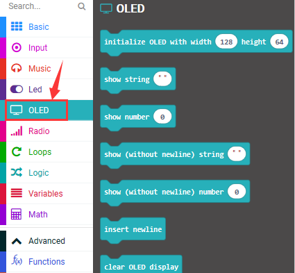

Test Results
Wire up according to connection diagram. plug in external power and upload code to micro:bit,the corresponding character and patterns are displayed on OLED.
Project 52: DHT11 Temperature And Humidity Sensor
Overview
This DHT11 temperature and humidity sensor is a composite sensor which contains a calibrated digital signal output of the temperature and humidity. Its technology ensures high reliability and excellent long-term stability.
In this experiment, we connected the signal end of the DHT11 temperature and humidity sensor to P0 of the micro: bit motherboard, and read the relevant data and calculate the temperature and humidity value in the current environment using a specific formula. We will display the calculated value on the serial monitor.
Components needed:
micro: bit motherboard * 1
Keyestudio Micro bit sensor V2 expansion board * 1
USB cable * 1
DHT11 temperature and humidity sensor * 1
Dupont jumper wire*3
Premium Battery Holder 6-cell AA*1
1.5V AA Battery*6
Connection Diagram

Test Code
Set test code with library file
Add library file in the following block
Search “DHT11”,as shown below, choose the first pattern, then automatically download and install library file.

After installing successfully, the corresponding block will be shown in the edit code column.


Test Results
Wire up according to connection diagram. plug in external power and upload code to micro:bit,Open CoolTerm, click Options and select SerialPort, set COM port and baud rate(115200). Click OK and Connect.
When DHT11 temperature and humidity sensor detects the temperature and humidity value, the results will be shown on CoolTerm monitor.

Project 53: IR Remote Control Decoding

Overview
There is no doubt that infrared remote control is commonly seen in our daily life. It’s hard to imagine our world without it.
An infrared remote control can be used to control a wide range of home appliances such as television, audio, video recorders and satellite signal receivers.
Well, in the following let’s get a better understanding of the infrared remote control.
Infrared remote control is composed of infrared transmitting and infrared receiving systems. That is, consist of an infrared remote control, an infrared receiver module and a microcontroller that can decode. You can refer to the figure below.

The 38K infrared carrier signal transmitted by an infrared remote controller is encoded by an encoding chip inside the remote controller. It is composed of a pilot code, user code, data code, and data inversion code.
The time interval between pulses is used to distinguish whether it is a signal 0 or 1. (when the ratio of high level to low level is about 1:1, considered as signal 0.) And the encoding is just well composed of signal 0 and 1.
The user code of the same button on remote controller is unchanged. Using difference data distinguish the key pressed on the remote control.
When press down a button on the remote control, it will send out an infrared carrier signal. And when infrared receiver receives that signal, its program will decode the carrier signal, and through different data codes, thus can judge which key is pressed.
The microcontroller is decoded by an received signal 0 or 1 to determine which key is pressed by the remote control.
Components Needed:
Micro: bit motherboard * 1
Keyestudio Micro bit sensor V2 expansion board * 1
USB cable * 1
Keyestudio Digital IR Receiver Module * 1
Keyestudio infrared remote control * 1
DuPont jumper wire*3
Premium Battery Holder 6-cell AA*1
1.5V AA Battery*6
Connection Diagram

Test Code
Use the library file to set test code.
Add the library file in the following block
Enter this website https://github.com/mworkfun/pxt-RI-receiver.git to search

After installing successfully, the corresponding block is in the edit the edit code column.


Note:
Some infrared remote controls don’t come with a battery and need to be configured by yourself. The battery model is CR2025.
Before testing, make sure that the infrared remote control is OK. There is a tip for you: open the camera of the mobile phone to point at the signal light of infrared remote control, then press the button of remote control. If you see a purple light flashing via the cellphone, which means that the IR remote control is OK.
Test Results
Code explanation: When the keys on IR remote are not pressed, CoolTerm monitor will refresh 0 ceaselessly; when pressed, the monitor will display the corresponding key values.
Wire up according to connection diagram. plug in external power and upload code to micro:bit, Open CoolTerm, click Options and select SerialPort, set COM port and baud rate(115200). Click OK and Connect.
Point IR remote control to IR receiver, press the button, and display the corresponding key value on serial monitor, as shown below:

Therefore, we mark the corresponding values of buttons on the remote control, as shown below.

Project 54: IR Remote Control RGB
Overview
In the previous experiment, we used an infrared receiver module and a micro: bit control board to decode the infrared remote control. After decoding, we got the corresponding values of each key on infrared remote control. Thus, we can control other external sensors / modules based on these data. In this experiment, we add an SMD RGB module and control LED of RGB module to display the corresponding color by infrared remote.
Components Needed:
Micro: bit motherboard * 1
Keyestudio Micro bit sensor V2 expansion board * 1
USB cable * 1
Keyestudio Digital IR Receiver Module * 1
keyestudio RGB LED Module * 1
Keyestudio infrared remote control * 1
DuPont jumper wire*7
Premium Battery Holder 6-cell AA*1
1.5V AA Battery*6
Connection Diagram

Test Code
Need to add library file, please refer to the previous lesson.


Notes:
Some infrared remote controls don’t come with a battery and need to be configured by yourself. The battery model is CR2025.
Before testing, make sure that the infrared remote control is OK. There is a tip for you: open the camera of the mobile phone to point at the signal light of infrared remote control, then press the button of remote control. If you see a purple light flashing via the cellphone, which means that the IR remote control is OK.
Test Results
Wire according to connection diagram, plug in external power and upload code to micro:bit, Point IR remote control at IR receiving head of expansion board, press the button. Press button, LED of RGB displays red color;press
 button,LED is green color;tap
 button,LED shows blue color;press
 button, LED is purple color;when the other buttons are pressed, LED is white.
Project 55: Fan Module
Overview
A Keyestudio L9110 fan module is included in the kit. Connect the INA INB interface of the fan module to the control terminal of the micro bit (with ANALOG IN function). We can control the direction and speed of the fan on the module by two interfaces. In the experiment, we control the fan on the module to rotate clockwise, stop, and counterclockwise.
Components Needed:
micro: bit motherboard * 1
Keyestudio Micro bit sensor V2 expansion board * 1
USB cable * 1
Keyestudio L9110 fan module * 1
Dupont jumper wire*4
Premium Battery Holder 6-cell AA*1
1.5V AA Battery*6
Connection Diagram

Test Code


Test Results
Wire according to connection diagram, plug in external power and upload code to micro:bit. The fan on the module rotates clockwise (relatively faster) for 1s; stops for 2s; rotates counterclockwise (relatively slower) for 1s, stops for 2s, and alternately.
Project 56: Knock Sensor
Overview
Sensors can be used to detect various common data in life, such as light, temperature, humidity, sound, vibration and so on. We can use sensors to sense external signals and then control other devices. Thus, we can do various interesting experiments.
In the experiment, we connect the knock sensor and the LED module to the micro bit control board. Control the external LED to turn on and off by knock sensor.
Components Needed:
Micro: bit motherboard * 1
Keyestudio Micro bit sensor V2 expansion board * 1
USB cable * 1
Keyestudio Knock Sensor Module
Keyestudio Digital White LED Module * 1
Dupont jumper wire*6
Premium Battery Holder 6-cell AA*1
1.5V AA Battery*6
Connection Diagram

Test Code

Test Results
Wire according to connection diagram, plug in external power and upload code to micro:bit,When the white sensor senses the knock signal, the LED on the external module lights up for 500ms, otherwise the LED turns off.
Project 57: Magic Light Cup Sensor
Overview
In this kit, there are two magic light cup sensors. Its the working principle is to adjust light by analog ports, so as to make two sensor change the brightness. The ball switch emits digital signals and triggers analog ports. Through the program, we can see the effect that two cups filled with light.
In the experiment, we connect two magic light cup sensors to the micro bit expansion board, and achieve the effect with micro bit control board.
Components Needed:
Micro: bit motherboard * 1
Keyestudio Micro bit sensor V2 expansion board * 1
USB cable * 1
Keyestudio Magic Light Cup Sensor * 2
DuPont jumper wire*6
Premium Battery Holder 6-cell AA*1
1.5V AA Battery*6
Connection Diagram

Test Code


Test Results
Wire up according to connection diagram. plug in external power and upload code to micro:bit,tilt the two magic light cup sensors at the same time, one LED of light cup gradually darkens, and the other one gradually lights up. On the contrary, when the two magic light cup modules are tilted to the other side, one of the LEDs gradually brightens and another one gradually dims, similarly the light shifts position.